Applications
—7A42
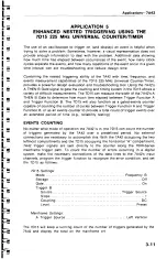
microprocessor
is
actually
latching
the
data
in.
The
7A42's
A THEN
B
mode will
be
used
to
create
a
“
nested"
trigger function.
Trigger
Function A must
first
arm
the
7A42
before
the
next
occurrence
of
Trigger
Function
B
will
generate a
trigger
output
signal.
In
this
application,
Trigger
Function A
looks
for a
low
level
on
the
read
strobe,
but
will
not
arm
the
trigger until
the
time
selected by
the
TRIGGER
FILTER
control
has
elapsed.
Trigger
Function
B
will
then
await
any
transition
on
the
data
line
during
the
remainder
of
the
strobe
pulse.
The
7D11
Digital
Delay
unit
can
be
used
to
reset
the
Trigger
Function
if
the
error
condition does
not
occur on
a
given
read
cycle.
For
this
measurement,
only
two of
the
7A42
input
channels
need
be
used.
CH1
can
be
connected
to
the
memory
“
Read"
line
and
CH2
can
monitor
the
“
Data"
line.
The
7A42
will “
babysit"
these
lines
and
trigger on
any
occurrence of
either
an
invalid
positive
or
negative
transition
on
the
Data
line
during
a
Read
operation.
If
the
7A42
produces
no
trigger
signal
the
stability
of
the
design
can
be
assured.
If a
trigger
does
occur,
the
7A42
will
display the
error
condition.
Timing
problems
that
recur
at
very
slow
repetition
rates,
and
happen
rarely
or
at
random
can
be
viewed
using
a
storage
oscilloscope.
A
fast-writing-rate
real-time
oscilloscope can
also
be
used
with
a
camera
to
record the event.
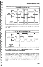
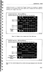
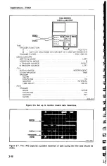
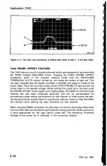
Figure 3-6
shows how to
set
up the
measurement
and
Figure
3-7
shows
the
display.
The
7A42
has
captured
a
data
line transition
10
nanoseconds
before the
end
of
the
read
cycle
during
the
time
that
data
should
remain
stable. Notice
that
no
trigger pulse
(TRIG
VIEW)
corresponds
to
the
falling data transition
that
occurrs
140
nanoseconds
into
the
next
read
cycle,
because
that
data transition
falls
within
the
time
that
the
data
may still change.
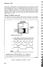
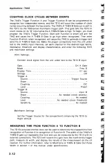
Trigger
Function
A
arms
when
a low
level Read
strobe
occurs
after
the
TRIGGER
FILTER
control
time
has
elapsed.
Trigger
Function
B
causes a
trigger
if,
during
the
remainder
of
the
low
level
Read
strobe,
either
a
positive
or a negative
transition
of
the
data
line
occurs.
The variable
TRIGGER
FILTER
control
should
be
used
to
prevent
arming
before
the
time
window
of
the
actual
"Read”
operation.
The
TRIGGER
FILTER
control
can
be
set
to
prevent
arming of
the
7A42 for
up
to
300
nanoseconds.
For
example,
with
the
TRIGGER
FILTER
control set
for
approximately
200
nanoseconds,
the
“
Read"
line
must
remain
low
longer
than
200
nanoseconds
in
order
for
Trigger
Function
A
to
be armed.
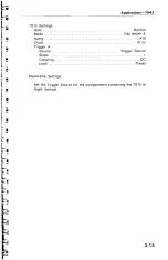
To set
the
TRIGGER
FILTER
control
for
200
nanoseconds,
select
Trigger
Function
A
with
the
TRIGGER
FILTER
control
turned
off
(fully
counterclockwise).
Note
the
pulse width
of
the Read
strobe.
Now
turn
the
TRIGGER
FILTER
control
clockwise
until
the
width
of
the
Read
strobe
is
shortened
by
200
nanoseconds.
The
triggering
is
now
at
that
point
of
the
Read
cycle
after
which
the
Data
lines
must
remain
stable.
The
TRIGGER FILTER
control
will
operate
only
on
Function
A.
because
Function
B
will
contain
an
edge
sensitive
channel.
(The
Trigger
Filter
responds
only
to
level-sensitive
Trigger
Functions.)
The
7D1
1
is
used
in
the
delay
by
time
mode.
It
begins
counting
when
Function
A
is
recognized
and
times
out
shortly
after
the end of
the
Read
strobe.
A
positive
transition
on
the
7A42's
A
THEN
B
Gate out will
start
the
7D1
1'
s
count. The
7D11
receives this
gate
signal internally
through
the
7000-series main
interface.
At
the
end
of
its programmed
time
interval,
the
7D11
resets
the
7A42.
This
enables
the
7A42
to prepare
for
the
next
event
even
if
Trigger Function
B
is
never
recognized.
3-7

