123
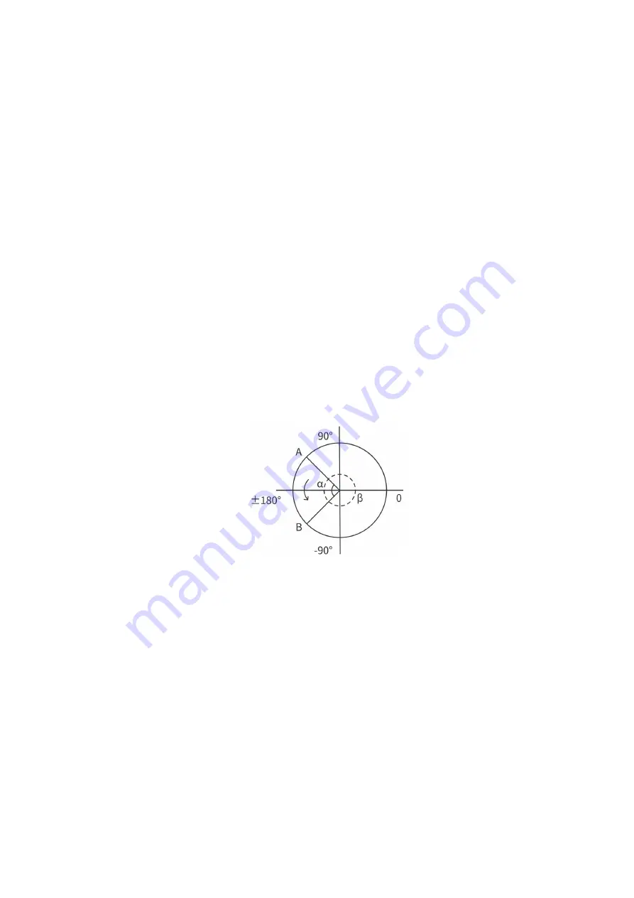
the shortest way to reach target orientation. In particular, it is
important to strictly control the magnitude of the deflection angle
between the two points to control the direction of rotation, and if
necessary, insert a third point between the two points. As shown in
figure 6.4, if a deflection is needed from position point A to point B,
the robotic arm moves in the direction of α angle. If the robotic arm
needs to be moved in the direction of the β angle, a new position
between the angles of β should be inserted, and the angle that
formed by the inserted point and A should be smaller than α.
●
The +180° and -180°points of the Roll/Pitch/Yaw are coinciding in
the space, and the valid range is ±180°, so it is possible to have
both ±180° when the robotic arm is reporting the position.
●
Roll angle, pitch angle, and yaw angle (RPY). The RPY rotation
matrix (X, Y', Z" rotation) is determined by the following formula:
R rpy (γ, β, α) = R Z (α) · R Y (β) · R X (γ)
Summary of Contents for 850
Page 1: ...1...
Page 72: ...72 4 The control box PC and network switch are connected by Ethernet ca ble...
Page 74: ...74 Step3 Open the Properties Step4 Open the IPV4...
Page 89: ...89 Cancel Cancel the selection Save Save the modified data Discard Discard the modified data...
Page 145: ...145 1 6 6 GPIO Control Box and End tool interface...
Page 149: ...149 1 6 7 End Effector...
Page 197: ...197 State 6 Stop Generally use studio will generate state 6 and state 6 is also a kind of stop...


