ML-x17 DATA LOGGER MANUAL
Manufacturers of low power instruments
page 54
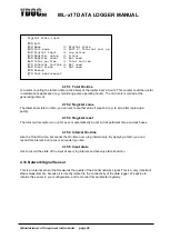
4.19.2.3
Register type
Consult the manual of your sensor for this. 3 types are supported:
-
Bit register
-
Holding register (default register)
-
Input register
4.19.2.4
Register Start address
MODBUS is a protocol to read from and write data to a memory map of a device, which is constructed of
a list of 16 bit registers. How this memory map is formatted is up to the manufacturer of the device.
Please specify the register in the memory map where the first parameter of your interest starts.
4.19.2.5
Data Type
The type of the data that is stored in the sensor @ the starting address. See table below.
Datatype
Size
Signed
Remarks
WORD
1 register (2 bytes)
unsigned
Short
1 register (2 bytes)
signed
DWORD
2 register (4 bytes)
unsigned
Integer
2 register (4 bytes)
signed
Float
2 register (4 bytes)
IEEE754
Double
4 register (8 bytes)
IEEE754
All multi register data types are also available for reversed logic (word swapping).
Consult the manual of your device to check with data type applies.
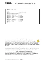
4.19.2.6
Parameters
Parameter 1
starts at the chosen ‘Start register’ and the next 1, 2 or 4 registers further, depending on the
chose
n ‘Data type’. You can read-out up to 20 parameters. However if you are not interested in some
positions or if do not appear in consecutive register order, you can skip these positions. If you want to
read-out more parameters, you can define another instance of the MODBUS-driver. You can like any
other parameter change its name, unit and more see: Chapter
4.2 Parameters_Parameters
4.19.2.7
Timing
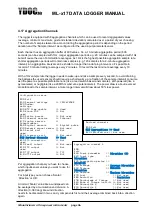
The logger expects the sensor to respond within 1 second after issuing a request an will try the request
up to 3 times if not.

