ADV8003 Hardware Manual
Rev. B, August 2013
112
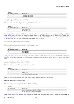
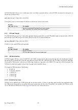
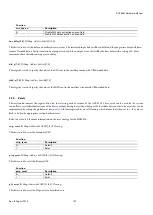
svsp_vid_clk_update
, IO Map,
Address 0x1A3F[4]
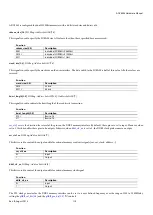
This bit is used to trigger the open loop period to be captured in the DPLL. A low to high transition triggers the action.
Function
svsp_vid_clk_update
Description
0
Do not update open_loop_period in DPLL
1
Update open_loop_period in DPLL
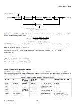
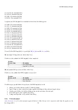
For example, the following procedure for updating the SVSP DPLL clock period is very similar to that of the PVSP:
1A 1A39 0A – Put the DPLL into ADV8003 mode
1A 1A40 XX – Configure DPLL clock period setting
1A 1A41 XX – Configure DPLL clock period setting
1A 1A42 XX – Configure DPLL clock period setting
1A 1A43 XX – Configure DPLL clock period setting
1A 1A3F 80 – Recommended setting
1A 1A3F 90 – Recommended setting
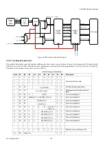
Once configured, the clock in
2.2.4.3.
Frame Tracking
The ADV8003 employs frame tracking on its scaler outputs. There will always be some error in the input frame rate versus the ideal frame
rate. This could cause frame drops or repeats at the output. Frame tracking allows the output timing to track the input timing in such a
way that eliminates frame drops and repeats while also remaining immune to discontinuities in the input. The system can be fully
frequency and phase locked using
. If phase locked is selected, there will be an integer frame latency from input to output. If
frequency locked is selected, there could be a non integer frame latency number from input to the output. Selecting phase error latency is
the recommended setting.
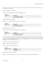
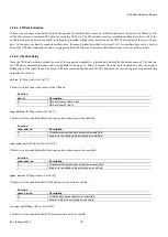
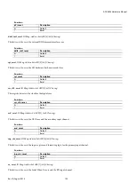
pvsp_err_sel,
IO Map,
Address 0x1A4EH
This bit is used to choose between phase locked loop and frequency locked loop for the Primary VSP frame tracking mode.
Function
pvsp_err_sel
Description
0
Phase error
1
Frequency error
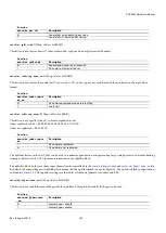
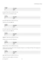
svsp_err_sel
, IO Map,
Address 1A4FH
This bit is used to choose between phase locked loop and frequency locked loop for the Secondary VSP frame tracking mode.
Function
svsp_err_sel
Description
0
Phase error
1
Frequency error
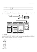
Frame tracking results in an integer ratio relationship between the input and output frame rates of 1:1, 2:1, 1:2, 5:2 or 2:5. For example, if
scaling from 1080p30 to 720p59.94 with frame tracking enabled, the resulting output may be 720p60 due to the 1:2 relationship.
Frame rate tracking is primarily intended for cases where the input frame rate and output frame rate have a 1:1 relationship or are close to
this target, that is, 59.94 Hz to 60 Hz. However, it can also be used for some standard frame rate conversion modes such as 24 Hz to 60
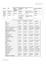
Hz, 25 Hz to 50 Hz, and 30 Hz to 60 Hz. The list of scaling conversions where frame tracking can be enabled is covered in
Summary of Contents for ADV8003
Page 366: ...ADV8003 Hardware Manual Rev B August 2013 366 Figure 144 ADV8003 Schematic Page 4...
Page 367: ...ADV8003 Hardware Manual Rev B August 2013 367 Figure 145 ADV8003 Schematic Page 5...
Page 368: ...ADV8003 Hardware Manual Rev B August 2013 368 Figure 146 ADV8003 Schematic Page 6...
Page 369: ...ADV8003 Hardware Manual Rev B August 2013 369 Figure 147 ADV8003 Schematic Page 7...
Page 371: ...ADV8003 Hardware Manual Rev B August 2013 371 Figure 149 ADV8003 Schematic Page 9...
Page 372: ...ADV8003 Hardware Manual Rev B August 2013 372 Figure 150 ADV8003 Schematic Page 10...
Page 373: ...ADV8003 Hardware Manual Rev B August 2013 373 Figure 151 ADV8003 Schematic Page 11...
Page 374: ...ADV8003 Hardware Manual Rev B August 2013 374 Figure 152 ADV8003 Schematic Page 12...
Page 375: ...ADV8003 Hardware Manual Rev B August 2013 375 Figure 153 ADV8003 Schematic Page 13...
Page 376: ...ADV8003 Hardware Manual Rev B August 2013 376 Figure 154 ADV8003 Schematic Page 14...
Page 377: ...ADV8003 Hardware Manual Rev B August 2013 377 Figure 155 ADV8003 Schematic Page 15...
Page 378: ...ADV8003 Hardware Manual Rev B August 2013 378 Figure 156 ADV8003 Schematic Page 16...
Page 379: ...ADV8003 Hardware Manual Rev B August 2013 379 Figure 157 ADV8003 Schematic Page 17...
Page 380: ...ADV8003 Hardware Manual Rev B August 2013 380 Figure 158 ADV8003 Schematic Page 18...
Page 381: ...ADV8003 Hardware Manual Rev B August 2013 381 Figure 159 ADV8003 Schematic Page 19...
Page 382: ...ADV8003 Hardware Manual Rev B August 2013 382 Figure 160 ADV8003 Schematic Page 20...
Page 383: ...ADV8003 Hardware Manual Rev B August 2013 383 Figure 161 ADV8003 Schematic Page 21...
Page 384: ...ADV8003 Hardware Manual Rev B August 2013 384 Figure 162 ADV8003 Schematic Page 22...
Page 385: ...ADV8003 Hardware Manual Rev B August 2013 385 Figure 163 ADV8003 Schematic Page 23...
Page 386: ...ADV8003 Hardware Manual Rev B August 2013 386 Figure 164 ADV8003 Schematic Page 24...
Page 387: ...ADV8003 Hardware Manual Rev B August 2013 387 Figure 165 ADV8003 Schematic Page 25...
Page 388: ...ADV8003 Hardware Manual Rev B August 2013 388 Figure 166 ADV8003 Schematic Page 26...
Page 389: ...ADV8003 Hardware Manual Rev B August 2013 389 Figure 167 ADV8003 Schematic Page 27...
Page 390: ...ADV8003 Hardware Manual Rev B August 2013 390 Figure 168 ADV8003 Schematic Page 28...
Page 391: ...ADV8003 Hardware Manual Rev B August 2013 391 Figure 169 ADV8003 Schematic Page 29...
Page 392: ...ADV8003 Hardware Manual Rev B August 2013 392 Figure 170 ADV8003 Schematic Page 30...
Page 393: ...ADV8003 Hardware Manual Rev B August 2013 393 Figure 171 ADV8003 Schematic Page 31...
Page 395: ...ADV8003 Hardware Manual Rev B August 2013 395 Figure 173 ADV8003 Layout Page 2...
Page 396: ...ADV8003 Hardware Manual Rev B August 2013 396 Figure 174 ADV8003 Layout Page 3...
Page 397: ...ADV8003 Hardware Manual Rev B August 2013 397 Figure 175 ADV8003 Layout Page 4...
Page 398: ...ADV8003 Hardware Manual Rev B August 2013 398 Figure 176 ADV8003 Layout Page 5...
Page 399: ...ADV8003 Hardware Manual Rev B August 2013 399 Figure 177 ADV8003 Layout Page 6...
Page 400: ...ADV8003 Hardware Manual Rev B August 2013 400 Figure 178 ADV8003 Layout Page 7...
Page 401: ...ADV8003 Hardware Manual Rev B August 2013 401 Figure 179 ADV8003 Layout Page 8...
Page 427: ...ADV8003 Hardware Manual Rev B August 2013 427 P 2 Z Z Z P 1 Z Z Z P 0 Z Z Z...

