ADV8003 Hardware Manual
Rev. B, August 2013
296
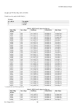
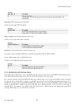
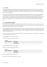
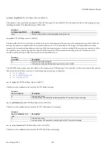
Function
cec_tx_retry_timeout_i
nt
Description
0
Interrupt not active
1
Interrupt active. CEC controller is indicating that the TX retry timeout has expired
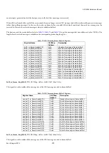
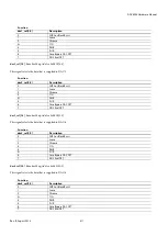
tx_nack_counter[3:0]
, TX2 CEC Map,
Address 0xF814[3:0] (Read Only)
The signal is used to specify the number of times that the NACK error condition was encountered while trying to send the current
message. This register is reset to 0b0000 when CEC_TX_ENABLE is set to 1.
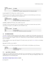
Function
tx_nack_counter[3:0]
Description
0000
No error condition
XXXx
Number of times NACK error condition was encountered
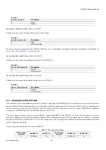
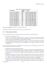
tx_lowdrive_counter[3:0]
, TX2 CEC Map,
Address 0xF814[7:4] (Read Only)
This signal is used to specify the number of times that the LOWDRIVE error condition was encountered while trying to send the
current message. This register is reset to 0b0000 when CEC_TX_ENABLE is set to 1.
Function
tx_lowdrive_counter[3:
0]
Description
0000
No error condition
XXXx
Number of times LOWDRIVE error condition was encountered
7.3.
CEC RECEIVE SECTION
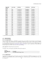
The receive section features the hardware required for the CEC module to act as a follower. Once the CEC module is powered up via the
bit, the CEC Rx section immediately begins monitoring the CEC bus for messages with the correct logical address(es).
When the message reception is completed, the CEC receive section generates an interrupt (assuming the corresponding interrupt mask
bits are set accordingly).
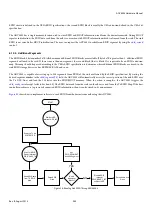
The host can disable message reception while keeping the CEC module powered up by using the
received messages.
force_nack
, TX2 CEC Map,
Address 0xF84B[1]
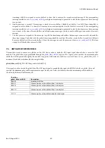
This bit is used to force NO-ACK control setting. This bit forces the CEC controller to not acknowledge any received messages.
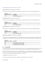
Function
force_nack
Description
0
ACK the relevant messages
1
NACK all messages
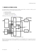
7.3.1.
Logical Address Configuration
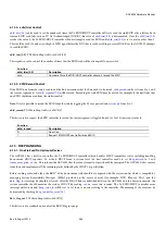
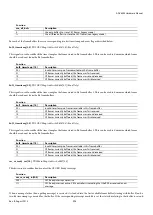
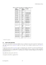
The host must set the destination logical address(es) that the CEC receive section will respond to. Up to three logical addresses can be
enabled allowing support for multi function devices such as DVD recorders with TV tuners which require multiple logical addresses. The
logical address(es) are set via the following registers:
Summary of Contents for ADV8003
Page 366: ...ADV8003 Hardware Manual Rev B August 2013 366 Figure 144 ADV8003 Schematic Page 4...
Page 367: ...ADV8003 Hardware Manual Rev B August 2013 367 Figure 145 ADV8003 Schematic Page 5...
Page 368: ...ADV8003 Hardware Manual Rev B August 2013 368 Figure 146 ADV8003 Schematic Page 6...
Page 369: ...ADV8003 Hardware Manual Rev B August 2013 369 Figure 147 ADV8003 Schematic Page 7...
Page 371: ...ADV8003 Hardware Manual Rev B August 2013 371 Figure 149 ADV8003 Schematic Page 9...
Page 372: ...ADV8003 Hardware Manual Rev B August 2013 372 Figure 150 ADV8003 Schematic Page 10...
Page 373: ...ADV8003 Hardware Manual Rev B August 2013 373 Figure 151 ADV8003 Schematic Page 11...
Page 374: ...ADV8003 Hardware Manual Rev B August 2013 374 Figure 152 ADV8003 Schematic Page 12...
Page 375: ...ADV8003 Hardware Manual Rev B August 2013 375 Figure 153 ADV8003 Schematic Page 13...
Page 376: ...ADV8003 Hardware Manual Rev B August 2013 376 Figure 154 ADV8003 Schematic Page 14...
Page 377: ...ADV8003 Hardware Manual Rev B August 2013 377 Figure 155 ADV8003 Schematic Page 15...
Page 378: ...ADV8003 Hardware Manual Rev B August 2013 378 Figure 156 ADV8003 Schematic Page 16...
Page 379: ...ADV8003 Hardware Manual Rev B August 2013 379 Figure 157 ADV8003 Schematic Page 17...
Page 380: ...ADV8003 Hardware Manual Rev B August 2013 380 Figure 158 ADV8003 Schematic Page 18...
Page 381: ...ADV8003 Hardware Manual Rev B August 2013 381 Figure 159 ADV8003 Schematic Page 19...
Page 382: ...ADV8003 Hardware Manual Rev B August 2013 382 Figure 160 ADV8003 Schematic Page 20...
Page 383: ...ADV8003 Hardware Manual Rev B August 2013 383 Figure 161 ADV8003 Schematic Page 21...
Page 384: ...ADV8003 Hardware Manual Rev B August 2013 384 Figure 162 ADV8003 Schematic Page 22...
Page 385: ...ADV8003 Hardware Manual Rev B August 2013 385 Figure 163 ADV8003 Schematic Page 23...
Page 386: ...ADV8003 Hardware Manual Rev B August 2013 386 Figure 164 ADV8003 Schematic Page 24...
Page 387: ...ADV8003 Hardware Manual Rev B August 2013 387 Figure 165 ADV8003 Schematic Page 25...
Page 388: ...ADV8003 Hardware Manual Rev B August 2013 388 Figure 166 ADV8003 Schematic Page 26...
Page 389: ...ADV8003 Hardware Manual Rev B August 2013 389 Figure 167 ADV8003 Schematic Page 27...
Page 390: ...ADV8003 Hardware Manual Rev B August 2013 390 Figure 168 ADV8003 Schematic Page 28...
Page 391: ...ADV8003 Hardware Manual Rev B August 2013 391 Figure 169 ADV8003 Schematic Page 29...
Page 392: ...ADV8003 Hardware Manual Rev B August 2013 392 Figure 170 ADV8003 Schematic Page 30...
Page 393: ...ADV8003 Hardware Manual Rev B August 2013 393 Figure 171 ADV8003 Schematic Page 31...
Page 395: ...ADV8003 Hardware Manual Rev B August 2013 395 Figure 173 ADV8003 Layout Page 2...
Page 396: ...ADV8003 Hardware Manual Rev B August 2013 396 Figure 174 ADV8003 Layout Page 3...
Page 397: ...ADV8003 Hardware Manual Rev B August 2013 397 Figure 175 ADV8003 Layout Page 4...
Page 398: ...ADV8003 Hardware Manual Rev B August 2013 398 Figure 176 ADV8003 Layout Page 5...
Page 399: ...ADV8003 Hardware Manual Rev B August 2013 399 Figure 177 ADV8003 Layout Page 6...
Page 400: ...ADV8003 Hardware Manual Rev B August 2013 400 Figure 178 ADV8003 Layout Page 7...
Page 401: ...ADV8003 Hardware Manual Rev B August 2013 401 Figure 179 ADV8003 Layout Page 8...
Page 427: ...ADV8003 Hardware Manual Rev B August 2013 427 P 2 Z Z Z P 1 Z Z Z P 0 Z Z Z...

