iSXblue/SXBlue II GNSS Series Technical Reference Manual
134
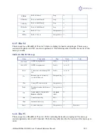
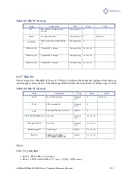
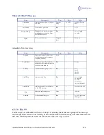
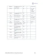
Table 6-11 Bin 99 Message
Group
Components
Type
Bytes
Value
NavMode2
Navigation mode data (lower 3
bits hold the GPS mode, upper bit
set if differential is available).
Byte
1
Lower 3 bits take on
the values
0 = time not valid
1 = no fix
2 = 2D fix
3 = 3D fix
Upper bit (bit 7) is 1
if differential is
Available
UTCTimeDiff
Whole seconds between UTC and
GPS time (GPS minus UTC)
Byte
1
Positive
GPSWeek
GPS week associated with this
message
Unsigned
short
2
0 to 65536
GPSTimeOfWeek
GPS tow (sec) associated with
this message
Double
8
0.0 to 604800.0
ChannelData
12 structures (see below)
containing tracking data for each
of the 12 receiver channels
Structure
array
12x24 =288
See following table
ClockErrAtL1
The clock error of the GPS clock
oscillator at L1 frequency in Hz
Short
2
-32768 to 32768
Spare
Not used at this time
Unsigned
short
2
Future use
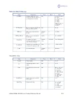
ChannelData Array
Group
Components
Type
Bytes
Value
Channel
Channel number
Byte
1
0 to 12
SV
Satellite being tracked, 0 == not
tracked
Byte
1
0 to 32
Status
Status bit mask (code carrier bit
frame)
Byte
1
Bit 0 = code lock
1 = carrier lock
2 = bit lock
3 = frame sync
4 = frame sync and
new epoch
5 = channel reset
6 = phase lock
7 = spare
LastSubFrame
Last sub frame processed in the
GPS message
Byte
1
1 to 5
EphmVFlag
Ephemeris valid flag
Byte
1
0 = not logged
1 = invalid
2 = valid
3 = has data (not
yet validated)

