


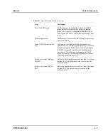


Firmware
Loading Application Software
PPC/PMC-8260/DS1
4 - 9
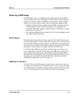
Preparing a ROM Image
The ROM image of max. 1.75 MByte must be programmed into the boot flash
device beginning at an offset of 256 KByte into the boot flash device which corre-
sponds to an effective address of FE040000
16
. The firmware considers a ROM
image to be valid and executes it only if one of the following conditions apply:
•
Checksum information was programmed into the ROM configuration section
and the checksum is valid. For further information, see descriptions for
CSUM_ID, IMG_SIZE, and IMG_CSUM in Table 11 “ROM Image Configu-
ration Section” on page 4-10.
•
No checksum information is present and the 32-bit value at ROM image offset
108
16
differs from FFFF.FFFF
16
.
SYPCR Register
By default, the firmware will not alter the contents of the System Protection and
Control (SYPCR) register of the PowerQUICCC II at power up, i.e. leaving the bus
monitor and the software watchdog enabled. A problem arises when the firmware
detects and executes a ROM image which does not provide support for the software
watchdog, i.e. the watchdog is not triggered and the board is then reset.
To be able to install ROM images without watchdog support, the firmware pro-
vides a mechanism to preset the SYPCR register for a ROM image’s purpose be-
fore executing it. The firmware presets the SYPCR register if you program the
fields SYPCR_WR and SYPCR_VAL of the ROM configuration section. For fur-
ther information, see SYPCR_WR and SYPCR_VAL descriptions in Table 11
“ROM Image Configuration Section” on page 4-10.
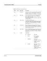
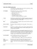
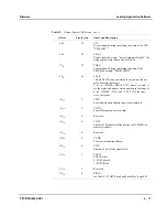
ROM Image Configuration
The first 256 bytes of a ROM image are considered as control section where you
can define how the firmware must handle the image. You can, for example, define
the SYPCR register value, POST execution speed and whether POST is executed
or not. The following table shows the offsets and values to be programmed.
Summary of Contents for PPC/PMC-8260/DS1
Page 1: ...PPC PMC 8260 DS1 Reference Guide P N 6806800B10A July 2006 ...
Page 8: ...viii PPC PMC 8260 DS1 ...
Page 22: ...xxii PPC PMC 8260 DS1 ...
Page 26: ...xxvi PPC PMC 8260 DS1 ...
Page 30: ...xxx PPC PMC 8260 DS1 ...
Page 31: ...1 Introduction ...
Page 32: ......
Page 39: ...2 Installation ...
Page 40: ......
Page 53: ...3 Indicators and Connectors ...
Page 54: ......
Page 64: ...On Board Connectors Indicators and Connectors 3 12 PPC PMC 8260 DS1 ...
Page 65: ...4 Firmware ...
Page 66: ......
Page 104: ...Code Examples Firmware 4 40 PPC PMC 8260 DS1 ...
Page 105: ...5 Memory Map and Devices ...
Page 106: ......
Page 132: ...Resetting the Devices Memory Map and Devices 5 28 PPC PMC 8260 DS1 ...
Page 133: ...6 TDM Channel Configuration ...
Page 134: ......
Page 145: ...A Troubleshooting ...
Page 146: ......
Page 148: ...A 4 PPC PMC 8260 DS1 ...
Page 150: ...I 2 PPC PMC 8260 DS1 ...


