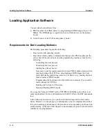


Loading Application Software
Firmware
4 - 20
PPC/PMC-8260/DS1
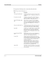
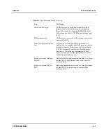
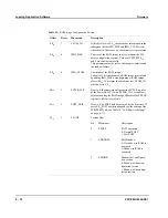
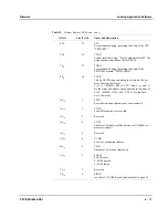
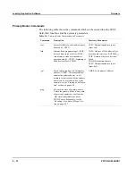
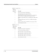
booter from reacting. The latter case can be detected by checking the alive state
(see Table 14 “Primary Booter Commands and Parameters” page 4-18).
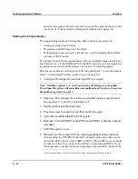
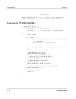
Starting the Primary Booter
The programming routine for starting the primary booter is necessary for:
•
Loading an image from PCI bus
•
Programming a ROM image into boot flash
•
Perfoming read/write accesses to I/O devices e.g. when reading the boot flash
contents or POST results.
The primary booter will start automatically if there is no ROM image present in the
boot flash device or if the ROMSKIP bit in the PCR register is set. Communication
is possible as soon as the LEDs indicate it (L1 is red, L2 is flashing green).
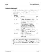
Program your software according to the following description
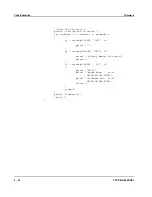
1)
to start the primary
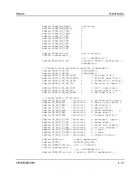
booter. A code example for this routine is given on page 4-33.
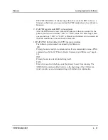
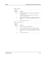
1. Configure PowerSpan II local interrupt INT5 as output
Note: Mailbox registers 5, 6, and 7 are used by the firmware. Using these
PowerSpan II registers will cause firmware malfunction. Therefore, do not use
the mailbox registers 5, 6 and 7.
2. Map one of PowerSpan II’s mailbox or doorbell registers (except mail-
box registers 5, 6, and 7) to interrupt pin 5
3. Enable mailbox/doorbell interrupt
4. Program access to respective mailbox/doorbell register
5. Set bits INI and ROMSKIP in PCR register
6. Optional: Set bits PSKIP to skip POST and WDDIS to disable software
watchdog
7. Set PSR register to zero
8. Deassert reset from local CPU by clearing pending mailbox interrupt
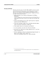
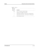
After resetting the PPC/PMC-8260/DS1 it should not take more than one sec-
ond for the PSR to be set either to RDY or POST. When POST is set, it should
not take more than 16 seconds for the self-test to complete and RDY to be set
(the actual time is usually much less, depending on the assembly options of the
1) This sequence assumes that PCI resources have already been assigned to the PowerSpan II.
Summary of Contents for PPC/PMC-8260/DS1
Page 1: ...PPC PMC 8260 DS1 Reference Guide P N 6806800B10A July 2006 ...
Page 8: ...viii PPC PMC 8260 DS1 ...
Page 22: ...xxii PPC PMC 8260 DS1 ...
Page 26: ...xxvi PPC PMC 8260 DS1 ...
Page 30: ...xxx PPC PMC 8260 DS1 ...
Page 31: ...1 Introduction ...
Page 32: ......
Page 39: ...2 Installation ...
Page 40: ......
Page 53: ...3 Indicators and Connectors ...
Page 54: ......
Page 64: ...On Board Connectors Indicators and Connectors 3 12 PPC PMC 8260 DS1 ...
Page 65: ...4 Firmware ...
Page 66: ......
Page 104: ...Code Examples Firmware 4 40 PPC PMC 8260 DS1 ...
Page 105: ...5 Memory Map and Devices ...
Page 106: ......
Page 132: ...Resetting the Devices Memory Map and Devices 5 28 PPC PMC 8260 DS1 ...
Page 133: ...6 TDM Channel Configuration ...
Page 134: ......
Page 145: ...A Troubleshooting ...
Page 146: ......
Page 148: ...A 4 PPC PMC 8260 DS1 ...
Page 150: ...I 2 PPC PMC 8260 DS1 ...


