Circuit Descriptions, Abbreviation List, and IC Data Sheets
9.
Audio Expander
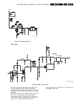
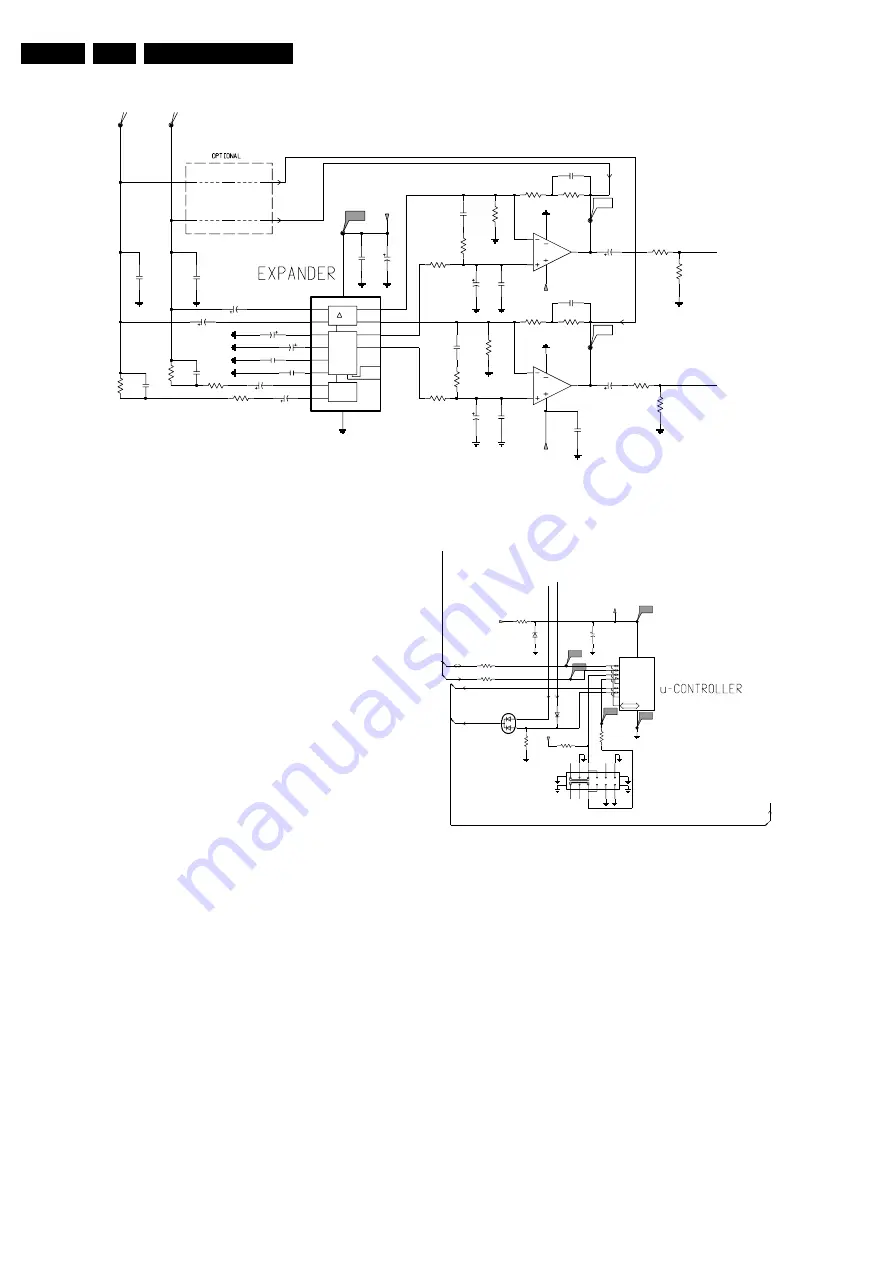
Figure 9-28 Expander circuit
The audio expander uses device SA572 (7770) that is intended
for high-end applications. It is used together with a low noise
OpAmp (7780).
There is an expanding factor of 2 in dB. There is a variable gain
cell (variable resistor) in the negative input of the OpAmp 7780
(NJM4565M). There is a rectifier cell that detects the input
voltage and translates into a current send to the gain cell .The
rectifier has an attack time constant and a decay time constant,
which is optimised to give the best auditive result.
If the input (V_in) rises with e.g. 2 times then the output will rise
4 times. This is because the negative input resistor formed by
the gain cell is decreased with a factor of two.
Remember that for an OpAmp V_out = V_in*((Rf+Rin)/Rin)
where Rf is constant (Rin= internal gain cell resistance).
Microcontroller
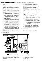
The microcontroller is an OTP Microchip PIC12C508A type
with 512-bit EPROM and six I/O lines. The controller has to be
programmed on the production line according the required
version of 433 or 864 MHz.
The main functions of the uP is reading the setting of the (4
position) slide switch within every 250 milliseconds, reading the
tuned info continuously, and start the power save mode if
necessary.
Figure 9-29 Microcontroller circuit
Frequency setting: This is necessary when the 4-position slide
switch is changed. In an internal look-up table, the four required
frequencies for the local oscillator are stored. The output
towards the synthesiser chip in the front-end is in I2C form. The
synthesizer is the only device on the bus. During frequency
setting the "mute" is active.
Scanning of the channel switch occurs within every 250
milliseconds (in any mode).
When "tuned" is going "high" in normal mode, the channel data
should be transmitted to the synthesizer to protect the receiver
in case of hang-up situations.
Muting: The "mute" of the receiver is controlled by the IF
receiver part, but can be overridden by the microcontroller.
The "mute" action initiated by the microcontroller is necessary
during channel switching and in the standby mode. Muting has
priority on all other main tasks. The hardware mute is the result
of an "AND" function between the “Tuned” and “Stereo”
information. The "tuned" information can be read by the
microcontroller on pin 2. The same pin has to be put in output
BUFFER
G
RECT
4n7
2782
2788
4n7
F707
F712
F713
18K
3781
3794
F707
F712
2770
4u7
2777
2u2
50V
100K
3793
3795
3796
47K
3788
2u2
3778
1K0
2783
50V
16V
10u
2780
3776
3K3
2776
2u2
50V
2773
2u2
50V
GOB
RCA
2
14 RCB
3 RIA
13 RIB
6
THTA
10
THTB
1
TRTA
15
TRTB
16
VCC
SA572D
7770
4 ACA
12 ACB
7 GIA
9 GIB
8
GND
5
GOA
11
270p
2795
22n
2771
2775
22n
F715
3792
100K
3797
F713
2784
220p
7780-A
3
2
1
8
4
7780-B
NJM4565M
5
6
7
8
4
NJM4565M
2u2
2785
50V
2772
220p
2793
220p
220p
2794
F714
47p
2762
2774
2786
10u 16V
1u
22n
2779
3786
2K2
3779
1K0
1K8
3789
BC847B
3783
1K8
50V
3775
2789
2u2
10K
10K
3771
3K3
3772
4u7
2787
4u7
2781
100K
3756
3755
100K
3782
47K
3787
18K
2778
1u
270p
2796
2K2
3780
RO
RO
LO
LO
+8V
+8V
+8V
CL36532008_085.eps
130503
GP1
T0CKI
VPP
MCLR
OSC2
OSC1
CLKIN
GP<0:5>
GP0
3753
1K0
F742
10
12
13
14
1
6
2
4
5
7
9
1765
SKR
3
8
11
3750
1K0
2754
4u7
35V
6751
BZX384-C5V1
F743
F744
6710
BAV70
F741
8
CTRL
PIC12C508A
7750
Φ
7
6
5
4
3
2
1
F740
3740
100K
3766
820R
3749
1K0
F742
3798
22K
F744
F743
F741
F740
6752
BAS316
{POWERSAVE,MUTE}
STEREO
MUTE
+5V
POWERSAVE
CL
DA
+5V
+10V
MUTE
TUNED
CL36532008_086.eps
130503

