PID Controller
CFW500 | 13-1
13
13 PID CONTROLLER
13.1 DESCRIPTIONS AND DEFINITIONS
The CFW500 features the PID Controller function, which can be used to control a closed loop process. This
function plays the role of a proportional, integral and differential controller which overrides the inverter regular
speed control.
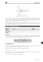
presents a scheme of the PID controller.
The process control is done by varying the motor speed, maintaining the process variable value (the one you wish
to control) at the desired value, which is set in the reference input (setpoint).
Application examples:
Flow or pressure control in a pipeline.
Temperature of a furnace or oven.
Chemical dosage in tanks.
The example below defines the terms used by the PID controller:
An electric pump in a water pumping system where the pressure must be controlled at the pump outlet pipe.
A pressure transducer is installed on the pipe and provides an analog feedback signal to the CFW500 that is
proportional to the water pressure. This signal is called process variable and can be viewed in parameter P0040.
A setpoint is programmed on the CFW500 via HMI (P0525) or via speed references as per
. The setpoint is the value desired for the water pressure regardless the variations in
demand of the system output.
NOTE!
When the setpoint is defined by a speed reference, the input unit in Hz is converted into the equivalent
percentage value of P0134.
The CFW500 will compare the setpoint (SP) to the process variable (VP) and control the motor speed so as to try
to nullify the error and keep the process variable equal to the setpoint. The setting of the gains P, I and D determine
the behavior of the inverter to eliminate this error.
The input variable operating scale of the PID controller: process variable (P0040) and setpoint (P0041) are defined by
P0528 and P0529. On the other hand, PID works internally with a percentage scale from 0.0 to 100.0 % according
to P0525 and P0533. Refer to
Both the setpoint (P0041) and the process variable (P0040) can be indicated via analog output AO1 or AO2, and
it is necessary to set P0251 or P0254 in 9 or 6, respectively. The full scale given by P0528 corresponds to 10 V
or 20 mA in the respective AOx output.
The PID or VP feedback can have as its source the analog inputs (P0203 = 1 for AI1 or P0203 = 2 for AI3) or
the frequency input FI (P0203 = 3). In case the selected reference for the setpoint is the same input that is being
used as PID feedback, the inverter will activate the Config Status. For further information, refer to
SITUATIONS FOR CONFIG STATUS on page 5-6
.
Once the PID Controller is active (P0203) and in Automatic mode (DIx and Bit 14 of P0680), the CFW500 HMI, in the
monitoring mode, will increment the value of P0525 in the main display by the keys
and
. This indication of
P0525 will depend on the band and shape as per P0528 and P0529. On the other hand if in Manual mode, the
HMI will increment the value of P0121 in Hz.
The Manual / Automatic command is done by one of the digital inputs DI1 to DI8, and the value 22 = Manual / Automatic
PID must be set in one of the respective parameters (P0263 to P0270). In case more than a DIx is programmed for
this function, the inverter will activate the Config Status (
Section 5.6 SITUATIONS FOR CONFIG STATUS on page
). In case no digital input is set, the PID controller will work only in the Automatic mode.
If the input programmed with the Manual / Automatic function is active, the PID will operate in the Automatic mode,
but if it is inactive, the PID will operate in the Manual mode. In this last case, the PID controller is disconnected
Summary of Contents for CFW500 V1.8X
Page 2: ......
Page 4: ......
Page 8: ...Contents...
Page 34: ...General Information 2 4 CFW500...
Page 38: ...About the CFW500 3 4 CFW500 3...
Page 42: ...HMI and Basic Programming 4 4 CFW500 4...
Page 52: ...Programming Basic Instructions 5 10 CFW500 5...
Page 56: ...Identification of the Inverter Model and Accessories 6 4 CFW500 6...
Page 76: ...Available Motor Control Types 8 4 CFW500 8...
Page 84: ...V f Scalar Control 9 8 CFW500 9...
Page 170: ...Communication 17 8 CFW500 17...


