CET Electric Technology
76
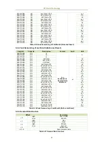
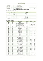
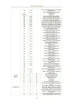
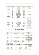
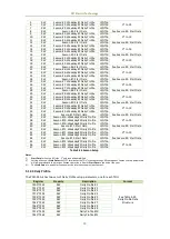
6506
RW
Active Delay
UINT16
0 to 9999 s, 10*
6507
RW
Inactive Delay
UINT16
0 to 9999 s, 10*
6508
RW
Trigger Action 1
2
UINT16
0 to 3
6509
RW
Trigger Action 2
2
UINT16
…
…
…
6580
RW
Setpoint #9
Setpoint Type
UINT32
0=Disabled*
1=Over Setpoint
2=Under Setpoint
6581
RW
Parameter
1
UINT16
0* to 29
6582
RW
Over Limit
Float
0*
6584
RW
Under Limit
Float
0*
6586
RW
Active Delay
UINT16
0 to 9999 s, 10*
6587
RW
Inactive Delay
UINT16
0 to 9999 s, 10*
6588
RW
Trigger Action 1
2
UINT16
0 to 3
6589
RW
Trigger Action 2
2
UINT16
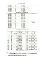
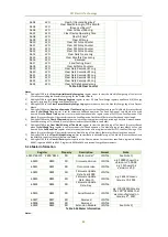
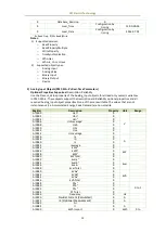
Table 5-39 Setpoint Setup Parameters
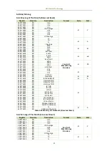
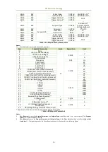
Notes:
1)
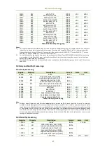
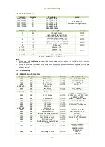
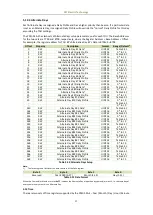
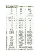
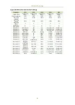
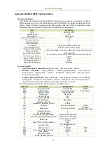
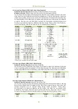
The table below illustrates the Setpoint Parameters.
Key
Setpoint Parameter
Scale
Resolution
Unit
0
None
-
-
-
1
Uln (Any Phase Voltage)
x1
0.001
V
2
Ull (Any Line Voltage)
3
I (Any Phase Current)
A
4
In (Calculated)
5
Frequency
0.01
Hz
6
P (kW Total)
0.001
W
7
Q (kvar Total)
var
8
S (kVA Total)
VA
9
PF (PF Total)
-
10
P DMD (kW Total Present Demand)
W
11
Q DMD (kvar Total Present Demand)
var
12
S (kVA Total Present Demand)
VA
13
P DMD Pred (kW Total Predicted Demand)
W
14
Q DMD Pred (kvar Total Predicted Demand)
var
15
S DMD Pred (kVA Total Predicted Demand)
VA
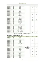
16
U THD
0.01%
100%
17
U TOHD
100%
18
U TEHD
100%
19
I THD
100%
20
I TOHD
100%
21
I TEHD
100%
22
U Unbal (Voltage Unbalance)
100%
23
I Unbal (Current Unbalance)
100%
24
Reversal (Any Phase Reversal)
1, 2
-
-
-
25
I4 (Measured)*
x1
0.001
A
26
AI*
1
-
27
IR (Residual Current) *
x1
0.001
A
28
U2 (Voltage Negative Sequence
Component)
x1
V
29
U0 (Voltage Zero Symmetrical Component)
* Appear only if the device is equipped with the appropriate option.
Table 5-40 Setpoint Parameters
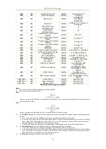
Notes:
5.
When Reversal is set as the Setpoint Parameter, the Setpoint Type should be set to 1 (i.e., Over Setpoint). The Setpoint
Type=2 (i.e., Under Setpoint) is invalid.
6.
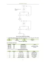
When Reversal is set as the Setpoint Parameter (with Setpoint Type=1), the Over Limit should be set as 0 and Under Limit
should be as 1. The logic diagram for the Phase Reversal setpoint is illustrated in the following figure:

