RP6 ROBOT SYSTEM - 4. Programming the RP6
To show you the basic principle, this example has been reduced to its essentials. A
state machine consists of different states and transitions between them. In our ex-
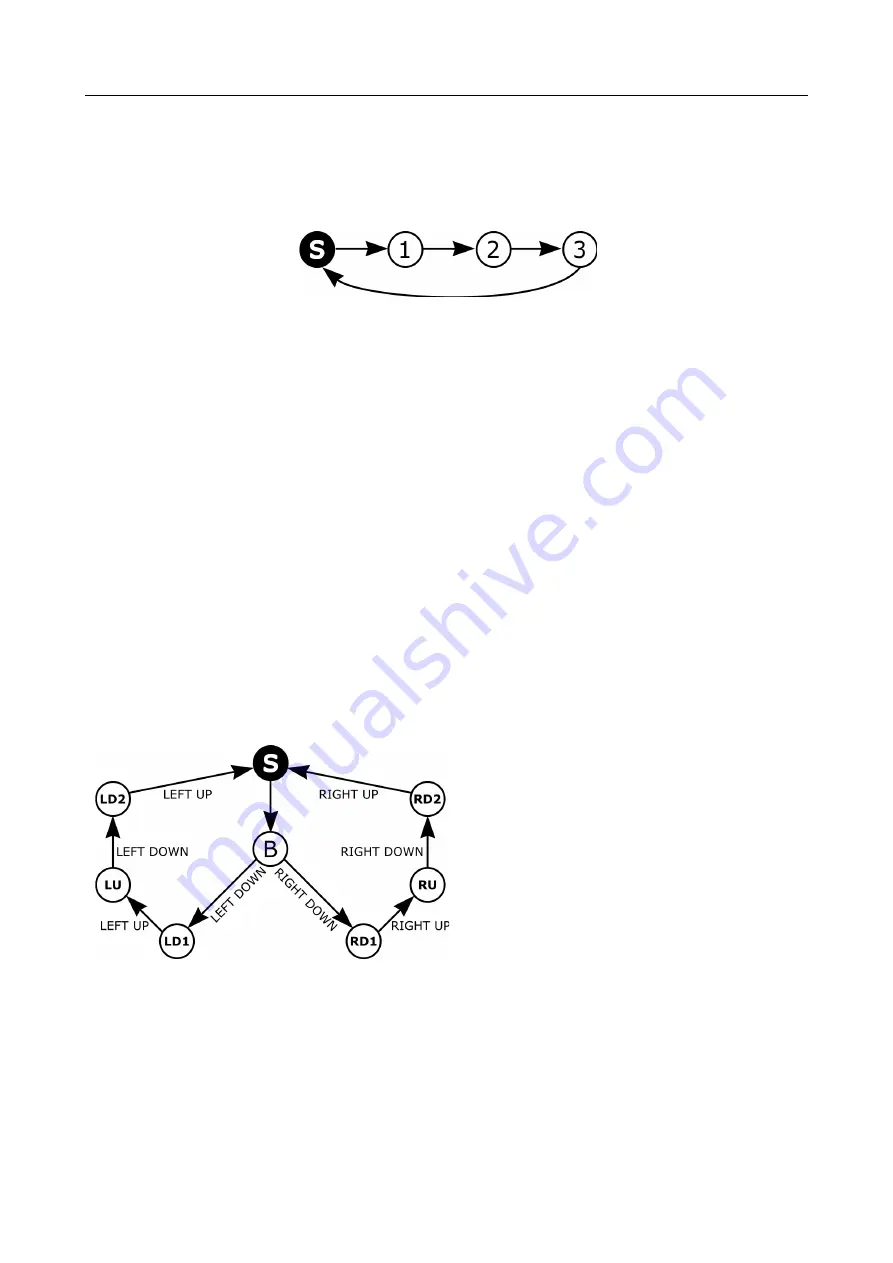
ample we have four states: STATE_START and STATE_1 up to 3. We may also visualize
the state machine above with the following graph:
“S” is the start state. We do not use any conditional state transitions here and there-
fore the system will change states up to state 3 and restart the sequence from state S
in each step. For better visualisation, there is a 500ms delay between the state
changes.
The program will generate the following output:
START
State 1
State 2
State 3
START
State 1
State 2
...
... etc.
The program may prolong this list endlessly.
The example program in file
RP6Base_Move_04_FSM.c
contains a more complex state
machine, featuring 8 states. The basic structure is shown in the following graph (in
this overview we abbreviated the labels of the states):
The state machine starts at state S and
immediately transits to state B (while
displaying a short text message). Having
arrived at state B the system will wait
until you hit one of the bumpers.
If you press down the left bumper, the
state machine will transit to state LD1
(“Left Down 1”) and to state RD1 on
pressing the right bumper. Now the next
transition has the condition that the
bumper is released again. If this hap-
pens, it will change state to either LU or RU. In both of these states, the machine will
only react on one of the bumper switches (left or right) and ignore any activities on
the other side. Only if you press the selected bumper once again, the state machine
will transit to the states RD2 and LD2, respectively. Releasing the bumper again, the
system returns to the S-state.
Of course this example program outputs an appropriate message for each state trans-
ition and will set the Status LEDs accordingly, but there was not enough space in the
graph for this additonal information. It just shows the general FSM layout.
- 116 -


