RP6 ROBOT SYSTEM - 2. The RP6 in detail
Immediately after the start-condition we have to send the 7 Bit long slave-address for
the device to be addressed, followed by a bit defining whether we want to write or
read data. The slave will respond by sending an ACK ("Acknowledge"). Any number of
data bytes may follow and each individual received byte will have to be acknowledged
by the slave (using the ACK-signal). Communication will be terminated with a
stop-condition.
This description is only a very short explanation of the I²C Bus. Interested readers
may find more information in the I²C Bus specification sheets by Philips. And also the
specs for the MEGA32 do contain more information to this topic.
The example programs demonstrate how to use the bus hardware. The RP6 library
already provides functions for controlling the I²C Bus. You will not have to go into de-
tails of the protocol, but it is useful to understand how bus the communication is ba-
sically working.
2.5.2. Expansion Connectors
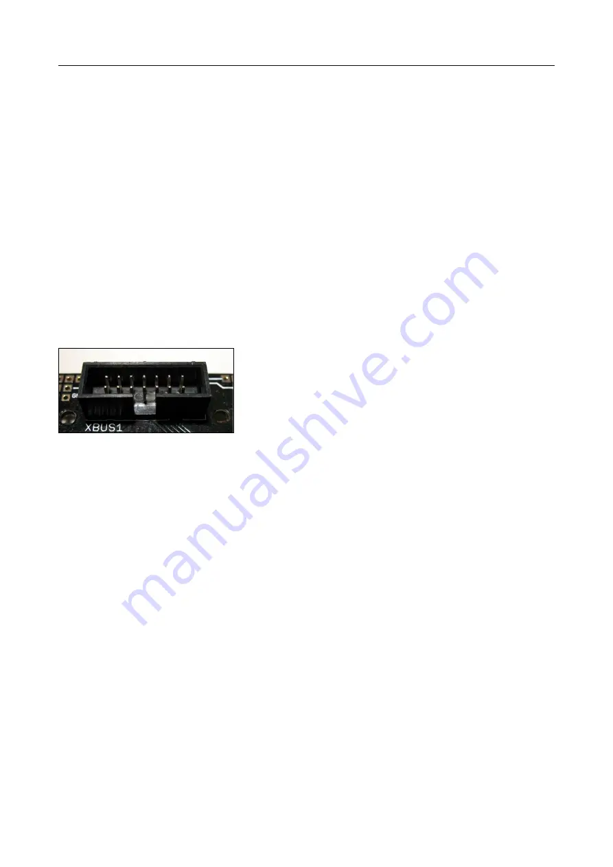
The mainboard provides four expansion connectors.
Two of these devices are labelled “XBUS1” and
“XBUS2” respectively. “XBUS” is a shortcut for “eXpan-
sion BUS”. “XBUS1” and “XBUS2” are interconnected
completely and have been arranged symmetrically on
the main board. For this reason you will be allowed to
mount expansion modules both at front and rear of
the robot. Each expansion module provides two XBUS connectors at one side of the
module. A 14-pin flat cable is used for interconnecting the modules to each other and
to the mainboard. For interconnections each expansion module provides
two
identical
interconnected plugs. The outer plug has to be used for downward interconnections,
whereas the inner plug has to be used for upward interconnections. This way you are
(theoretically) allowed to stack any number of modules (see figure, showing three
RP6 breadboard expansion modules, which may be used for your individual circuits).
The XBUS plugs provide power supply, the previously described I²C-Bus, a master rest
and interrupt signals.
The power supply provides two voltages at the connectors: first of all the stabilized 5V
from the voltage regulator, but the battery voltage as well. The battery voltage will
vary with time and load – usually between 5.5 (discharged batteries) up to approxim-
ately 8.5V (newly charged batteries – varying from manufacturer to manufacturer).
Voltages may however exceed these limits depending on load, type and charging
status of batteries.
The master reset signal is important for resetting all microcontroller devices when
pressing the Start/Stop-button or for programming. The boot loader programs in the
microcontrollers will start their user program at a low pulse (high-low-high) on SDA.
This way all programs on the (AVR) controllers will simultaneously start after pressing
and releasing the Start/Stop-button or by starting the program by boot loader soft-
ware... (the boot loader does not only generate a low impulse to start, but also a
complete I²C General Call with 0 as data byte.)
- 27 -


