RP6 ROBOT SYSTEM - 2. The RP6 in detail
the obstacles!
Apart from sensor circuits, additional controllers could be useful to perform additional
tasks, e.g. the RP6 CONTROL M32 providing an extra MEGA32 microcontroller.
Of course the expansion system has to be capable of connecting several expansion
modules (see figure), while using a minimum number of signal lines and providing
sufficient communication speed.
2.5.1. The I²C Bus
The I²C Bus will satisfy these requirements. The name stands for
Inter Integrated
Circuit
Bus and is pronounced
I-squared-C.
Sometimes we may write “I2C” instead of
“I²C”, because in plain C language the “²” symbol is not allowed for variable names
and other things. The bus requires only two signal lines and may connect 127 parti-
cipants communicating at a rate of 400kBit/s.
The extremely popular I²C Bus, designed by Philips Semiconductors during the
eighties and nineties, is used in a great number of electronic equipment, e.g. video re-
corders, televisions, but also in industrial systems. Most of the modern PCs and note-
books use a variant of this bus called SMBus to control air flow and temperature of the
internal devices. A great number of robots also uses the I²C Bus system and for this
reason a number of sensor modules like ultrasonic sensors, electronic compasses,
temperature sensors and similar devices are available on the market.
The I²C Bus is a master/slave-oriented bus. One or more master devices are con-
trolling communication with up to 127 slave devices. But even though the bus is able
to handle multi-master communication, we will only describe a bus communication
with a single master device. Multi-master topology would only complicate things.
The two required signal lines are named SDA and SCL. SDA is to be read "Serial Data"
and SCL is named "Serial Clock" – which already explains we are using a data- and a
clock signal line. SDA is used as a bidirectional signal and therefore both master and
slave devices are allowed to output data. SCL is completely controlled by the master
device.
Data bits are always transferred synchronous to the clock signal as delivered by the
master. The SDA level is only allowed to change as long as SCL is low (except for
Start- and Stop-conditions, see below). Transfer rates are allowed to change between
0 and 400kBit/s even while data is being transmitted.
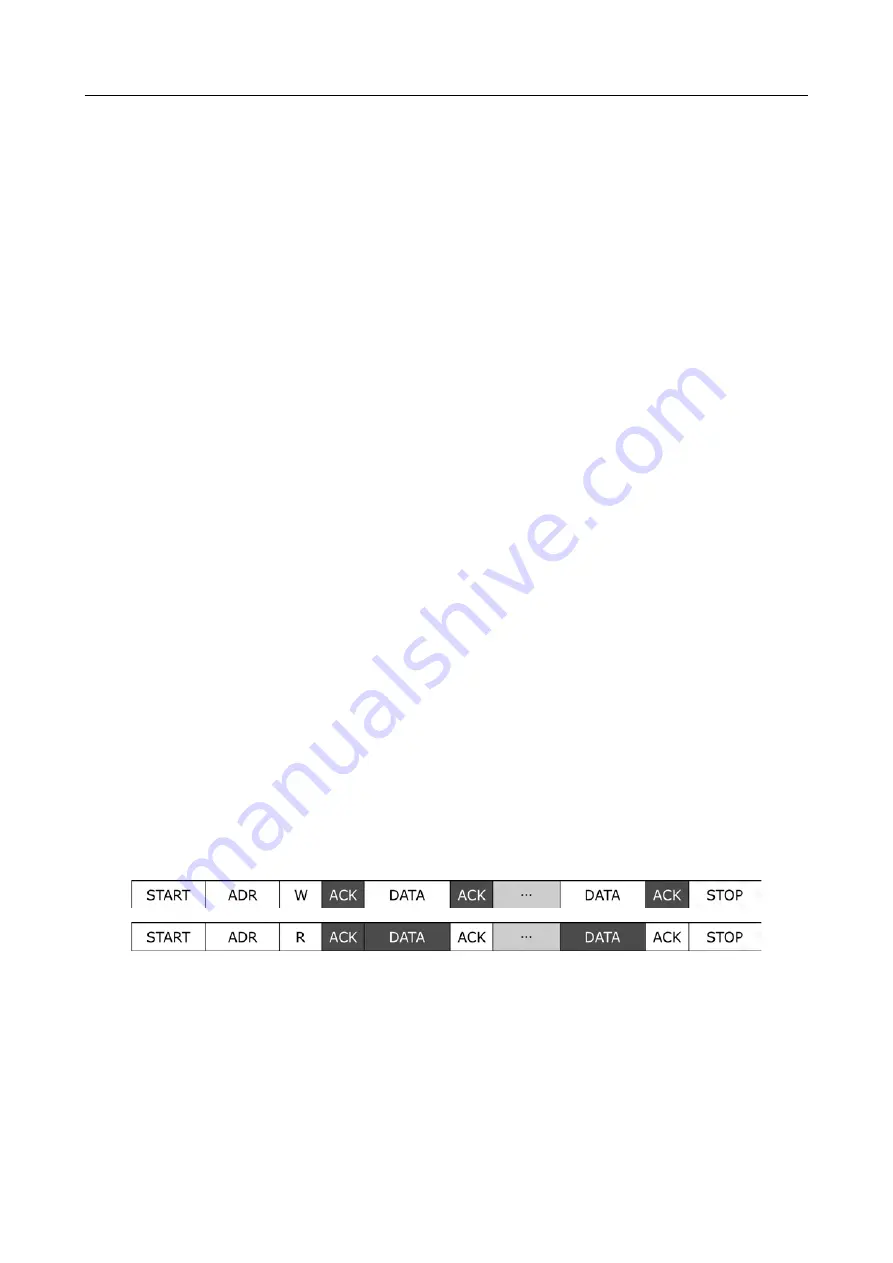
The preceding figures show usual transmission protocols. The first one shows a trans-
mission from a master to a slave device, in which white boxes refer to data transmis-
sions from master to slave and the dark boxes represent the responses from the slave
device.
Each transmission has to start with an initial start condition and must be ended by a
stop condition. The start condition is raised whenever at a high SCL-level the data line
SDA is pulled from high to low level. A reversed level pattern applies to the stop-con-
dition: whenever at a high SCL-level the data line SDA is pulled from low to high level
we meet a stop-condition.
- 26 -


