


Developer’s Manual
January, 2004
79
Intel XScale® Core
Developer’s Manual
Configuration
The format of LDC and STC for CP14 is shown in
Table 7-2
. LDC and STC follow the
programming notes in the ARM Architecture Reference Manual. Note that access to CP15 with
LDC and STC will cause an undefined exception and accesses to all other coprocessors is defined
in the Intel XScale
®
core implementation option section of the ASSP architecture specification.
LDC and STC transfer a single 32-bit word between a coprocessor register and memory. These
instructions do not allow the programmer to specify values for opcode_1, opcode_2, or Rm; those
fields implicitly contain zero, which means the performance monitoring registers are not
accessible.
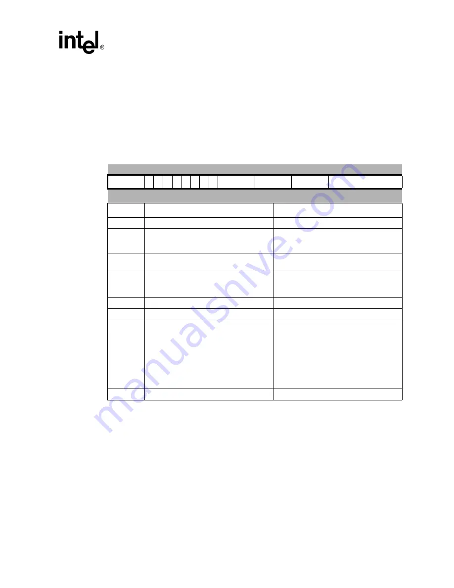
Table 7-2.
LDC/STC Format when Accessing CP14
31 30 29 28 27 26 25 24 23 22 21 20 19 18 17 16 15 14 13 12 11 10
9
8
7
6
5
4
3
2
1
0
cond
1
1
0
P U N W L
Rn
CRd
cp_num
8_bit_word_offset
Bits
Description
Notes
31:28
cond
- ARM* condition codes
-
24:23,21
P, U, W
- specifies 1 of 3 addressing modes
identified by addressing mode 5 in the
ARM
Architecture Reference Manual
.
-
22
N
- should be 0 for CP14 coprocessors. Setting
this bit to 1 has will have an undefined effect.
20
L
- Load or Store
0 = STC
1 = LDC
-
19:16
Rn
- specifies the base register
-
15:12
CRd
- specifies the coprocessor register
-
11:8
cp_num
- coprocessor number
The Intel XScale
®
core defines the following:
0b1111 = Undefined Exception
0b1110 = CP14
NOTE:
Refer to the Intel XScale
®
core
implementation option section of the
ASSP architecture specification to find
out the meaning of the other
encodings.
7:0
8-bit word offset
-


