FEC920: USER GUIDE
Page 123
September 18
Parameter path
Description
Type
Hex
Dec
Resolution
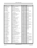
2 = Safe not acknowledged
3 = Active not acknowledged
Channel.1.Alarm1.Threshold
Alarm threshold
float32
1843
6211
Same as Channel.1.Main.PV
Channel.1.Alarm1.Type
Alarm type
uint8
1840
6208
Not applicable
0 = None
1 = Abs High
2 = Abs Low
3 = Dev high
4 = Dev Low
5 = Dev band
6 = ROC rising
7 = ROC falling
10 = Dig Off
11 = Dig high
12 = Dig Low
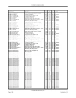
Channel.1.Alarm2.Acknowledge
1 = Acknowledge alarm
bool
01b1
433
Not applicable
Channel.1.Alarm2.Acknowledgement
1 = Alarm acknowledged
bool
1870
6256
Not applicable
Channel.1.Alarm2.Active
1 = Alarm source active, or safe but not ack’d
bool
186b
6251
Not applicable
Channel.1.Alarm2.Amount
Alarm amount
float32
1868
6248
Same as Channel.1.Main.PV
Channel.1.Alarm2.AverageTime
Average time
time_t
186a
6250
Set by Network.Modbus.TimeFormat
Channel.1.Alarm2.Block
Blocking enable (0 = Off; 1 = On)
uint8
1862
6242
Not applicable
Channel.1.Alarm2.ChangeTime
Change time (0 = Per second; 1= Per minute; 2 =Per hour)
uint8
1869
6249
Not applicable
Channel.1.Alarm2.Deviation
Alarm deviation
float32
1867
6247
Same as Channel.1.Main.PV
Channel.1.Alarm2.Dwell
Alarm dwell
time_t
1865
6245
Set by Network.Modbus.TimeFormat
Channel.1.Alarm2.Hysteresis
Alarm hysteresis
float32
1864
6244
Same as Channel.1.Main.PV
Channel.1.Alarm2.Inactive
1 = the alarm is safe and acknowledged
bool
186e
6254
Not applicable
Channel.1.Alarm2.Inhibit
1 = the alarm is inhibited
bool
1871
6257
Not applicable
Channel.1.Alarm2.Latch
Configures the latching type of the alarm (As Alarm1.Latch)
uint8
1861
6241
Not applicable
Channel.1.Alarm2.NotAcknowledged
1 = the alarm has not been acknowledged
bool
186f
6255
Not applicable
Channel.1.Alarm2.Reference
Alarm reference
float32
1866
6246
Same as Channel.1.Main.PV
Channel.1.Alarm2.Status
As Alarm1.Status
uint8
0103
259
Not applicable
Channel.1.Alarm2.Threshold
Alarm threshold
float32
1863
6243
Same as Channel.1.Main.PV
Channel.1.Alarm2.Type
Alarm type (as Alarm1.Type
uint8
1860
6240
Not applicable
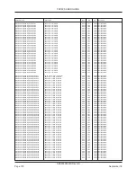
Channel.1.Main.CJType
Cold junction compensation type
uint8
180c
6156
Not applicable
0 = None
1 = Internal
2 = External
3 = Remote (Ch1)
4 = Remote (Ch2)
5 = Remote (Ch3)
6 = Remote (Ch4)
Channel.1.Main.CloseString
Close String
string_t
4990
18832
Not applicable
Channel.1.Main.Descriptor
Text string to describe the channel
string_t
4900
18688
Not applicable
Channel.1.Main.ExtCJTemp
External CJ temperature
float32
180d
6157
1dp
Channel.1.Main.FaultResponse
Fault response. 0 = none; 1 = Drive high; 2 = Drive low
uint8
1810
6160
Not applicable
Channel.1.Main.Filter
Filter time constant
float32
180e
6158
1dp
Channel.1.Main.InputHigh
Input range high value
float32
1804
6148
1dp
Channel.1.Main.InputLow
Input range low value
float32
1803
6147
1dp
Channel.1.Main.InternalCJTemp
Channel internal cold junction temperature
float32
1815
6165
1dp
Channel.1.Main.IPAdjustState
Input Adjust state (0 = Unadjusted; 1 = Adjusted)
bool
1816
6166
Not applicable
Channel.1.Main.IPAdjustState2
Secondary Input Adjust state (0 = Unadjusted; 1 = Adjusted)
bool
181c
6172
Not applicable
Channel.1.Main.LinType
Linearization type
uint8
1806
6150
Not applicable
0 =Type B
1 = Type C
2 = Type D
3 = Type E
4 = Type G2
5 = Type J
6 =Type K
7 = Type L
8 = Type N
9 = Type R
10 = Type S
11 = Type T
12 = Type U
13 = NiMoNiCo
14 = Platinel
15 = NiNiMo
16 = Pt20RhPt40Rh 17 = User 1
18 = User 2
19 = User 3
20 = User 4
21 = Cu10
22 = Pt100
23 = Pt100A
24 = JPT100
25 = Ni100
26 = Ni120
27 = Cu53
28 = Linear
29 = Sqrt
30 = x
3/2
32 = x
5/2
Channel.1.Main.MeasuredValue
Input value before linearization, scaling, adjust etc.
float32
1814
6164
Set by Channel.1.Main.Resolution
Channel.1.Main.MeasuredValue2
Measured value of the secondary input
float32
1819
6169
Set by Channel.1.Main.Resolution
Channel.1.Main.Offset
Fixed value to be added to/subtracted from PV
float32
1817
6167
3dp
Channel.1.Main.Offset2
Secondary input offset (as above).
float32
1818
6168
3dp
Channel.1.Main.OpenString
Open String
string_t
496c
18796
Not applicable
Channel.1.Main.PV
The process variable (output) of the channel
float32
0100
256
Set by Channel.1.Main.Resolution
Channel.1.Main.PV2
The secondary input process variable (output) of the channel
float32
0110
272
Set by Channel.1.Main.Resolution
Channel.1.Main.RangeHigh
Range high value
float32
1808
6152
Set by Channel.1.Main.Resolution
Channel.1.Main.RangeLow
Range low value
float32
1807
6151
Set by Channel.1.Main.Resolution
Channel.1.Main.RangeUnits
Range units: 0 = °C; 1 = °F; 2 = Kelvins
uint8
1809
6153
Not applicable
Channel.1.Main.Resolution
Specifies the resolution/number of decimal places
uint8
1801
6145
Not applicable
Channel.1.Main.ScaleHigh
Scale high value
float32
180b
6155
Set by Channel.1.Main.Resolution
Channel.1.Main.ScaleHigh2
Scale high value for the secondary input
float32
181b
6171
Set by Channel.1.Main.Resolution
Channel.1.Main.ScaleLow
Scale low value
float32
180a
6154
Set by Channel.1.Main.Resolution
Channel.1.Main.ScaleLow2
Scale low value for the secondary input
float32
181a
6170
Set by Channel.1.Main.Resolution
Channel.1.Main.SensorBreakType
Sensor break type: 0 =Off; 1 = Low; 2 = High
uint8
180f
6159
Not applicable
Channel.1.Main.SensorBreakVal
Sensor break value
uint8
1811
6161
Not applicable
Channel.1.Main.Shunt
Shunt value (Ohms)
float32
1805
6149
2dp
Channel.1.Main.Status
The PV (output) status
uint8
0101
257
Not applicable
0 =Good
1 = Off
2 = Over range
3 = Under range
4 = HW error
5 = Ranging
6 = Overflow
7 = bad
8 = HW exceeded
9 = No data
12 = Comm channel error
Channel.1.Main.Status2
The secondary input PV (output) status (as above)
uint8
0111
273
Not applicable
Channel.1.Main.TestSignal
Channel test waveform
uint8
1802
6146
Not applicable
0 = Triangle 5hr
1 = Triangle 40 min
2 = Triangle 4 min
3 = Triangle 40 sec
4 = Sine 5 hr
5 = Sine 40 min
6 = Sine 4 min
7 = Sine 40 sec
Channel.1.Main.Type
Specifies the type of channel
uint8
1800
6144
Not applicable
A5E45696052A Rev-AA


