IP482 Industrial I/O Pack User’s Manual Counter Timer Module
__________________________________________________________________
_________________________________________________________________________________________
Acromag, Inc. Tel:248-295-0310 Fax:248-624-9234 Email:solutions@acromag.com http://www.acromag.com
20
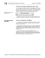
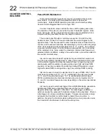
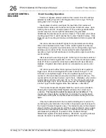
An interrupt can be generated upon index reload, or when the counter
value equals the constant value stored in the Counter Constant A Register.
Interrupts must be enabled via the interrupt enable bit-15 of the Counter
Control Register. The interrupt type must also be selected via bits 10 and
11 of the Counter Control Register. The interrupt will remain pending until
released by setting the required bit of the Counter/Timer Interrupt
Status/Clear
register or setting bit-15 of
the Counter Control register to “0”.
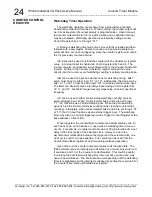
Note that interrupts in Quadrature Position Measurement are generated
whenever the interrupt conditions exists. If a pending interrupt is cleared,
but the interrupt conditions still exists, another interrupt will be generated.
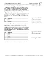
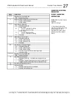
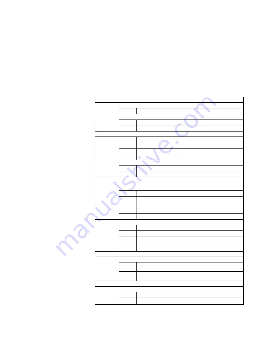
Bit(s)
FUNCTION
2,1,0
Specifies the Counter Mode:
001
Quadrature Position Measurement
3
Output Polarity (Output Pin ACTIVE Level):
0
Active LOW (Default)
1
1
Active HIGH
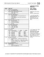
5, 4
InA / Channel A
00
Disabled (Default)
01
X1 Encoding
10
X2 Encoding
11
X4 Encoding
6
InB / Channel B
0
Disabled (Default)
1
Enabled
9,8,7
InC / Index: Channel Interrupt/Reload occurs when Index
signal=1 and the A & B input signals are as selected below.
See Control bits 11 & 10 for additional interrupt/load control.
000
Disabled (Default) 101, 110, and 111 also Disable
001
A = 0 , B = 1
010
A = 1 , B = 0
011
A = 1 , B = 1
100
A = 0 , B = 0
11,10
Interrupt Condition Select
00
No Interrupt Selected
01
Interrupt on counter equal Constant A Register.
10
Interrupt on Index and reload on Index
11
Interrupt on Index but do not reload counter on
Index.
12
Not Used (bit reads back as 0)
13
Input Debounce Enable
0
Disabled (Default)
– No Debounce Applied to any
Input.
1
Enabled
– Reject A, B, or Index Pulses less than
or equal to 2.5
s.
14
Not Used (bit reads back as 0)
15
Interrupt Enable
0
Disable Interrupt Service (Default)
1
Enable Interrupt Service
COUNTER CONTROL
REGISTER
QUADRATURE
POSITION
MEASUREMENT
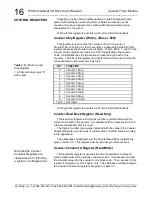
Table 3.10:
Counter Control
Register
(Quadrature Position
Measurement)
1. The default state of the
output pin is high (output has
pullup resistor installed). Bit 3
specifies the active output
polarity when the output is
driven.
The quadrature
measurement value can be
read from the Counter Read
Back Register.


