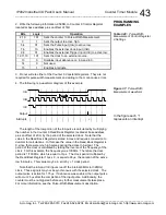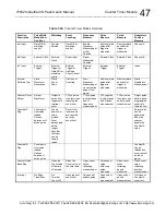
IP482 Industrial I/O Pack User’s Manual Counter Timer Module
__________________________________________________________________
_________________________________________________________________________________________
Acromag, Inc. Tel:248-295-0310 Fax:248-624-9234 Email:solutions@acromag.com http://www.acromag.com
38
3. Write the 16-bit value 3H to Counter 3 Constant A Register located at
base address plus an offset 34H for the non-active portion of the pulse, and
1H to Counter 3 Constant B Register located at base address plus an offset
48H for the active portion of the pulse.
In order to determine the necessary Counter Constant values first
calculate the period of the selected clock (internal or external). The period
is calculated by taking the inverse of the clock frequency. In this case,
1/500KHz is equal to 2
s. Then take the total time for the low portion of the
pulse and divide it by the clock period. For this example, 6
s/2
s is equal to
3. Convert this value to Hex and the result is the total count that is placed in
the appropriate Counter Constant Register. Since it has been stipulated
that the pulse is active high, 3H is written to Counter 3 Constant A Register,
which contains the value for the non-active (low) portion of the pulse. The
same procedure is used to calculate the Constant B value. Take the total
period of the high portion of the pulse and divide it by the period of the clock.
Here 2
s/2
s is equal to 1. Converting to hex, 1H is written to Counter 3
Constant B Register since it contains the active (high) portion of the pulse.
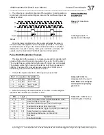
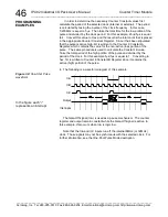
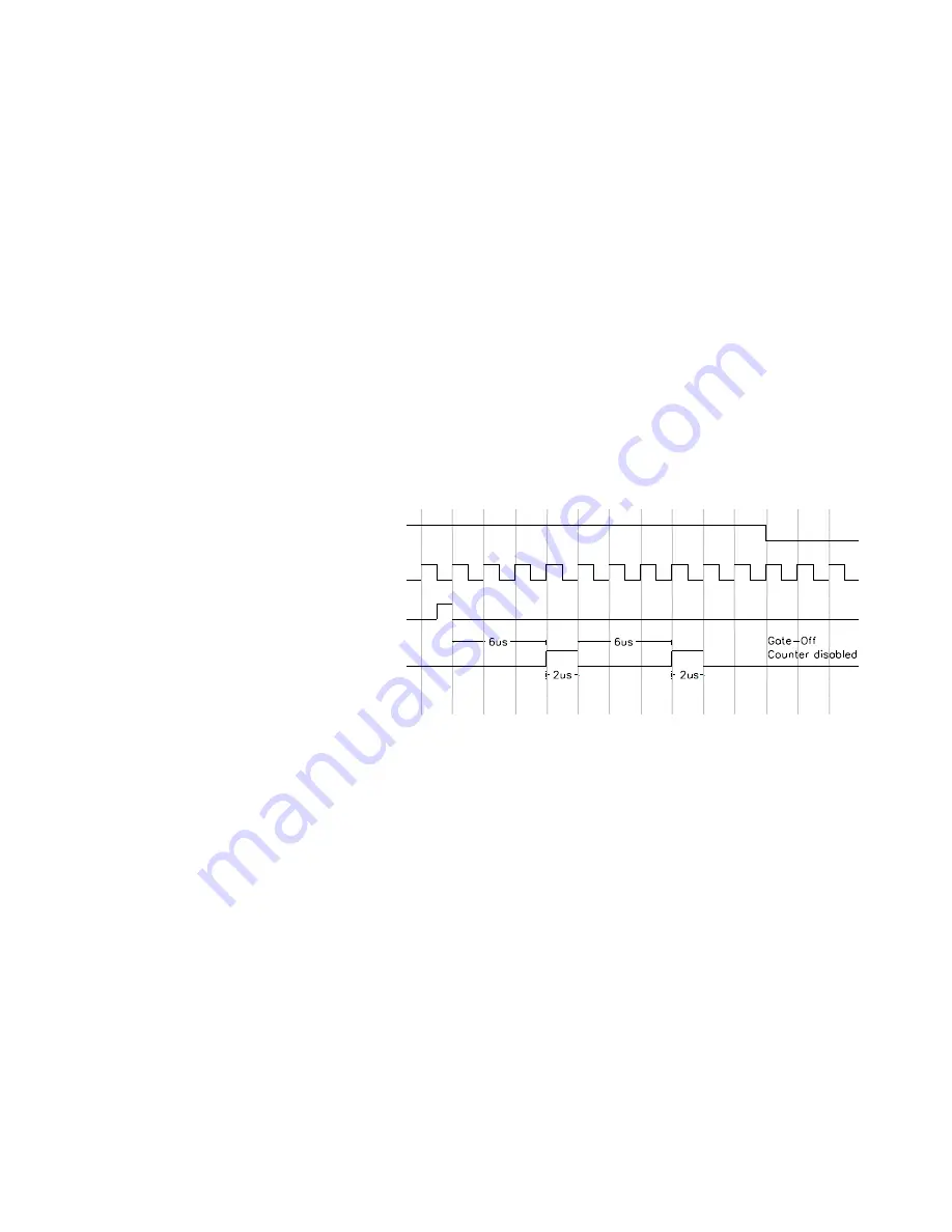
4. The following is a waveform diagram of this example.
i
i
i
i
Output
InB
InC
InA
Interrupts
Note that the InA and InC inputs run off the internal 8MHz (or 32MHz)
clock. Those signals may not be synchronous with the selected clock. For
further information, see the Pulse Width Modulation Operation description.
Watchdog Timer Operation Example
The objective for this example is to create a Watchdog Timer with a
countdown length of 10
s using 16-bit Counter 5 with an external active
high counter reload, clock, and active low trigger signals. The output is
active high. Assume the external clock has a frequency of 500KHz. The
counter reload and trigger signals are periodic. Additionally, debounce and
interrupts are enabled.
PROGRAMMING
EXAMPLES
Figure 3.3:
PWM waveform
In the figure an “i”
represents an interrupt

