IP482 Industrial I/O Pack User’s Manual Counter Timer Module
__________________________________________________________________
_________________________________________________________________________________________
Acromag, Inc. Tel:248-295-0310 Fax:248-624-9234 Email:solutions@acromag.com http://www.acromag.com
36
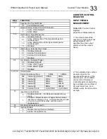
The following section provides sample applications for each of the
counter modes of operation. This includes I/O pin assignments, register
settings, required calculations, and waveform diagrams. All examples
assume 8MHz carrier operation, even addressing, and that all values are
read and written in hex. These assumptions may differ depending on the
system and software being used.
Quadrature Position Measurement Example
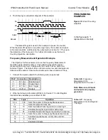
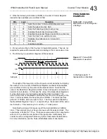
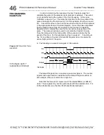
The objective for this example is to employ Quadrature Position
Measurement using 16-bit Counter 1. Suppose that an encoder, connected
to the shaft of a motor, provides three signals. Two of the signals (A and B)
are out of phase by 90
and provide directional information. For this
example, Channel A will always lead B. The third signal C is an Index pulse
that is active every four revolutions (A pulses). Assume that X2 encoding is
used and on the index pulse, when Channel A and B are equal to one, an
active high output and interrupt are generated, and the counter is reloaded
to zero. Additionally, debounce is enabled.
1. Connect the inputs/output to the following pins (unpowered):
Pin # Connection
Description
1
In1_A(+)
Channel A
11
In1_B(+)
Channel B
21
In1_C(+)
Index
33
Out1(+)
Output
2. Write the following information, A9E9H, to Counter 1 Control Register
located at base address plus an offset of 08H.
Bits
Logic
Operation
2,1,0
001
Sets the counter to Quadrature Position Measurement.
3
1
Sets the output to active high.
5,4
10
Sets encoding to X2 and enables Channel A (InA).
6
1
Enables Channel B (InB).
9,8,7
011
Sets the Index condition to occur when A=1 and B=1.
11,10
10
Provides for interrupt and reload to occur on index.
12
0
Not used.
13
1
Enables input debounce on InA, InB, and InC.
14
0
Not used.
15
1
Enables interrupts.
3. Write the 16-bit value 0H to Counter 1 Constant B Register located at
base address plus an offset 44H for the counter reload value.
The Constant B Register contains the reload value of the counter.
Therefore, in this example, when an index pulse occurs and Channel A and
B are equal to one, the counter loads zero. This value relies on the specific
application.
While Counter Constant A is not used in this example, it has other
applications in Quadrature Position Measurement. Refer to the description
of Quadrature mode for further information.
PROGRAMMING
EXAMPLES
Table 3.18:
Quadrature Pin
Assignments for Counter 1
Note: Make sure all inputs
and outputs are properly
grounded.
Table 3.19:
Quadrature
Counter Control Register 1
Settings

