IP482 Industrial I/O Pack User’s Manual Counter Timer Module
__________________________________________________________________
_________________________________________________________________________________________
Acromag, Inc. Tel:248-295-0310 Fax:248-624-9234 Email:solutions@acromag.com http://www.acromag.com
44
Input Period Measurement Example
The objective for this example is to use the Input Period Measurement
operation using 16-bit Counter 9. The high-to-low transition of the input
signal will begin measurement. Additionally, the counter has an external
clock and an active high External Trigger. The output of the counter is
active high and interrupts are enabled. Assume the external clock has a
frequency of 250KHz.
1. Connect the inputs/output to the following pins (unpowered):
Pin # Connection
Description
9
In9_A(+)
Pulse Input
19
In9_B(+)
Ext. Clock
29
In9_C(+)
Ext. Trigger
41
Out9(+)
Output
2. Write the following information, 965EH, to Counter 9 Control Register
located at base address plus an offset of 18H.
Bits
Logic
Operation
2,1,0
110
Sets the counter to Input Period Measurement.
3
1
Sets the output to active high.
5,4
01
Sets the Pulse input (InA) to active low.
7,6
01
Enables the external clock input (InB).
9,8
10
Enables the external Trigger Input (InC) to active high.
12,11,10
101
Sets the clock to an external source.
13
0
Disables input debounce on InA and InC.
14
0
Not used.
15
1
Enables interrupts.
3. Do
not
write to either of the Counter 9 Constant Registers. They are not
required for input period measurement and writing to them can cause errors.
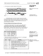
4. The following is a waveform diagram of this example.
i
Output
InB
InC
InA
Interrupts
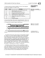
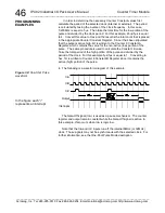
The period of one cycle of the InA waveform is calculated by multiplying
the number in the Counter 9 Read Back Register, located at the base
address plus an offset of 2CH, by the period of the selected clock. Note that
the value in the Read Back Register is stored in Hex and requires
conversion to decimal for calculations. In this case the value in the Counter
PROGRAMMING
EXAMPLES
Table 3.30:
Input Period
Measurement Pin
Assignments for Counter 9
Note: Make sure all inputs
and outputs are properly
grounded.
Table 3.31:
Input Period
Measurement Control Register
9 Settings
Figure 3.8:
Input Period
Measurement waveform
In the figure each “i”
represents an interrupt


