IP482 Industrial I/O Pack User’s Manual Counter Timer Module
__________________________________________________________________
_________________________________________________________________________________________
Acromag, Inc. Tel:248-295-0310 Fax:248-624-9234 Email:solutions@acromag.com http://www.acromag.com
26
Event Counting Operation
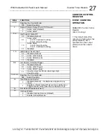
Positive or negative polarity events can be counted. Event Counting is
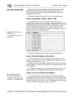
selected by setting Counter Control Register bits 2 to 0 to logic “100” and
setting bits 12 to 10 to logic “000”.
Input pulses or events occurring at the input InB of the counter will
increment the counter until it reaches the Counter Constant A value. Upon
reaching the count limit, an output pulse of 1.75
s will be generated at the
counter output pin, and an optional interrupt may be generated.
Additionally, the internal event counter is cleared. The counter will continue
counting, again from 0, until it reaches the Counter Constant A value. Once
triggered, event counting will continue until disabled via Control register bits
2 to 0.
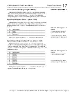
InA can be used as a Gate-Off signal to stop and start event counting.
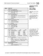
When InA is enabled via bits 5 and 4 of the control register for active low
Gate-Off input, a logic low input will enable event counting while a logic high
will stop event counting. When InA is enabled for active high Gate-Off
operation, a logic high will enable event counting while a logic low will stop
event counting.
InB is used as the event input signal. Active high or low input events can
be selected via Control register bits 7 and 6. A minimum event pulse width
(InB) of 125ns is required for correct pulse detection with input debounce
disabled. Programmable clock selection is not available in event counter
mode.
InC can be used to either control up/down counting or as an external
trigger input. When control register bits 9 and 8 are set to logic “11”, InC
functions as an Up/Down signal. When the Up/Down signal is high the
counter is in the count down mode (when low the counter counts up). The
counter will not count down below a count of zero. Alternately, when control
register bits 9 and 8 are set to logic “01” or “10”, the InC input functions as
an external trigger input. Event counting may also be internally triggered
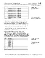
(via the Trigger Control Register at the base a offset 04H).
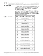
The Counter Constant A Register holds the count-to value (constant).
Reading the Counter Read Back Register will return the current count
(variable).
The Counter Constant A value must not be left as 0
. The
counter upon trigger starts counting from 0 and since the counter would
match the count-to value the counter resets and starts counting from zero
again.
If the Interrupt Enable bit of the Counter Control Register is set (bit 15),
an interrupt is generated when the number of input pulse events is equal to
the Counter Constant A register value. The internal counter is then cleared
and will continue counting events until the counter constant A value is again
reached and a new interrupt generated. An interrupt will remain pending
until released by setting the required bit of the Counters Interrupt
Status/Clear
register at the base a offset 02H. A pending interrupt
can also be cleared, by setting Control register bit-15 to logic low.
COUNTER CONTROL
REGISTER

