PACSystems™ RX3i DNP3 Outstation User Manual
Section 5
GFK-3103B
June 2020
System Operation
56
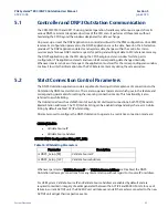
When SOE channel mask value is set to 1 the configured Event mode as per the configuration (SOE or
MOST_RECENT) is applicable, If the mask value is set to 0, then the configured Event Mode is set to
MOST_RECENT.
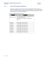
The mask
‘x’ indicates the channel number
. The bit value [0 through 7] indicates channels numbers [1
through 8] (if the user has enabled white-listing for the IP address). Otherwise, the bit value [0 through
7] indicates the channel numbers [1 to 8].
For example, if number of channels on the CPE115 is 4, parameter mDNP3_Setup [29].x =
2#0000000000000011, and if IP Address white-listing is enabled, the Master 1 and Master 2 will use
the configured Event Mode (SOE or MOST_RECENT). Master 3 and Master 4 will set the Event Mode to
MOST_RECENT. However, if white-listing is disabled, then any of the 2 Masters will have the configured
Event mode and the other 2 Masters will have Event mode set to MOST_RECENT.
5.5
CROB Control Feature
This feature is provided to support different control codes like PULSE ON/OFF, CLOSE, TRIP and LATCH
ON/OFF for the CROB Control objects. This is implemented using additional CROB configuration. These
configurations provide a mechanism for passing on the CROB control information like Control code and
Control information coming from the DNP3 Master to the Controller Application logic, which can be
used for generating desired commands.
5.5.1
CROB Control Definition
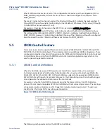
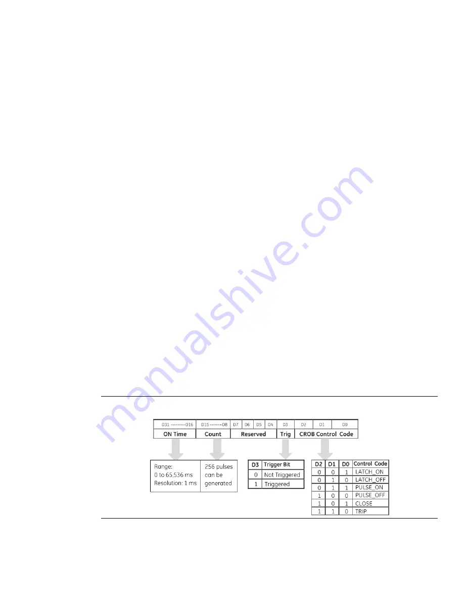
When the Outstation receives a CROB operate command from a master station, the associated
Command parameters like Point Number, Pulse Duration Time, Count and Control Type (PULSE_ON,
PULSE_OFF, LATCH_ON, LATCH_OFF , TRIP and CLOSE) are updated in the appropriate CROB Control
DWord (32-bit) and Trigger bit is set, refer to Figure 14. The Controller logic can then check the trigger
bit and generate the required command as per the Control Code.
For example, when the Pulse CROB command is issued by the master station, then the Outstation
receives the command and updates CROB Control DWord with all command parameters. The user logic
can generate a pulse command as per the trigger bit and pulse duration parameters. The user logic
needs to clear the trigger bit for any subsequent operation.
Figure 14: CROB Control DWord Layout
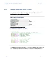
The following are the parameters for the CROB Control DWord:

