FC6A S
ERIES
MICROS
MART
L
ADDER
P
ROGRAMMING
M
ANUAL
FC9Y-B1726
27-21
27: F
LOW
C
ALCULATION
I
NSTRUCTIONS
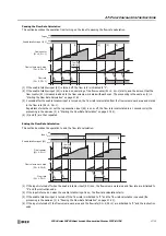
Pausing the Flow Rate Calculation
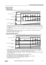
This section describes the operation from turning on the input to pausing the flow rate calculation.
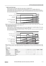
Ending the Flow Rate Calculation
This section describes the operation to end the flow rate calculation.
(1) If the enable totalizer input (S2) is turned off, the flow rate is initialized to "0".
(2) If the enable totalizer input (S2) is turned on, sampling of the flow counter (S1+0, S1+1) starts, and the amount that the
flow counter (S1) increased is added to the flow volume work area with each scan. The processing is the same as (2) in
"Starting the Flow Rate Calculation" on page 27-20.
(3) 1 second after the enable totalizer input is turned on, the flow rate is calculated from the flow volume work area and stored
in the flow rate (D1+0, D1+1).
Regardless of whether or not the log execution input (S3) is on or off, the flow rate is calculated in a 1 second cycle (the
processing is the same as (3) in "Starting the Flow Rate Calculation" on page 27-20).
(4) (2) and (3) are then repeated.
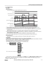
(1) If the input is turned off when the enable totalizer input (S2) is on, the flow volume work area and flow rate are initialized to
"0" and the instruction ends.
(2) If the input is turned on when the enable totalizer input is on, the flow rate calculation starts.
(3) If the enable totalizer input is turned off, the flow rate is initialized to "0" and the flow rate calculation is paused (the
processing is the same as (1) in "Pausing the Flow Rate Calculation" on page 27-21).
(4) If the input is turned off, the flow volume work area and the flow rate (D1+0, D1+1) are initialized to "0" and the instruction
ends.
Enable totalizer input (S2)
Input
ON
OFF
Flow counter
(S1+0, S1+1)
ON
OFF
Flow volume work area
(D1+8, D1+9)
Flow rate
(D1+0, D1+1)
(1)
(2)
(3)
(4)
1 s
Flow rate
update cycle
Flow rate
update cycle
Flow rate
update cycle
Enable totalizer input (S2)
Input
ON
OFF
Flow counter
(S1+0, S1+1)
ON
OFF
Flow volume work area
(D1+8, D1+9)
Flow rate
(D1+0, D1+1)
(1)
(2)
(3)
(4)
1 s
Flow rate
update cycle
Flow rate
update cycle
Flow rate
update cycle
Summary of Contents for MICROSmart FC6A Series
Page 1: ...B 1726 7 FC6A SERIES Ladder Programming Manual ...
Page 8: ...Preface 7 FC6A SERIES MICROSMART LADDER PROGRAMMING MANUAL FC9Y B1726 ...
Page 32: ...1 OPERATION BASICS 1 20 FC6A SERIES MICROSMART LADDER PROGRAMMING MANUAL FC9Y B1726 ...
Page 96: ...3 INSTRUCTIONS REFERENCE 3 18 FC6A SERIES MICROSMART LADDER PROGRAMMING MANUAL FC9Y B1726 ...
Page 130: ...4 BASIC INSTRUCTIONS 4 34 FC6A SERIES MICROSMART LADDER PROGRAMMING MANUAL FC9Y B1726 ...
Page 192: ...9 SHIFT ROTATE INSTRUCTIONS 9 12 FC6A SERIES MICROSMART LADDER PROGRAMMING MANUAL FC9Y B1726 ...
Page 272: ...12 DISPLAY INSTRUCTIONS 12 24 FC6A SERIES MICROSMART LADDER PROGRAMMING MANUAL FC9Y B1726 ...
Page 284: ...14 REFRESH INSTRUCTIONS 14 6 FC6A SERIES MICROSMART LADDER PROGRAMMING MANUAL FC9Y B1726 ...
Page 502: ...25 DATA LOG INSTRUCTIONS 25 22 FC6A SERIES MICROSMART LADDER PROGRAMMING MANUAL FC9Y B1726 ...
Page 546: ...26 SCRIPT 26 44 FC6A SERIES MICROSMART LADDER PROGRAMMING MANUAL FC9Y B1726 ...
Page 598: ...APPENDIX A 14 FC6A SERIES MICROSMART LADDER PROGRAMMING MANUAL FC9Y B1726 ...

