Page 146 of 163
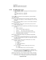
; (d/20) : dmx/20 giving fixture number
; %16 : isolates lower 4 bits
; 16- : reverses the 4 bits
; 9. Second variable passed is (d/20)/16
; (d/20) : dmx/20 giving the fixture number
; /16 : isolates the upper 4 bits.
;DEVICEADDRESS
"Handle %2d"h
"Fixture %11s"n
"DMX %03d"d
""
"Dip Switch 1234 5678"
"Personality 0000 0000"
"Address %b%b%b%b %b001"d/20%2,d/40%2,d/80%2,d/160%2,d/320%2
""
"0=OFF ( Right )"
"1=ON ( Left )"
DAEND
MINDMX=1
MAXDMX=481
DIVBY=20
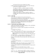
The next example is for a Colour Fader, This instrument uses a
GROUP and ADDRESS switch
; Upto 10 lines of 79 chars are allowed including formulae
; variables used d=dmx number, h=handle, n=devicename;
"Address %04b %1b001"16-(d/20%16),(d/20)/16
; This is the address display line
; 1. Items in quotes are displayed
; 2. First item here (Address ) is ascii text
; 3. %04b = 4 bits of binary data, 0 means dislay leading 0's
; 4. next is a space
; 5. %1b = 1 bit of binary data
; 6. 001 is ascii text again
; 7. Close quotes
; 8. first variable passed is 16-((d/20)%16)
; (d/20) : dmx/20 giving fixture number
; %16 : isolates lower 4 bits
; 16- : reverses the 4 bits
; 9. Second variable passed is (d/20)/16
; (d/20) : dmx/20 giving the fixture number
; /16 : isolates the upper 4 bits.
;
DEVICEADDRESS
"Handle %2d"h
"Fixture %11s"n
"DMX %03d"d
""
"GROUP %2d"d/12+1
"CHANNEL %2d"d%12
""
""
""
""
DAEND
MINDMX=1
MAXDMX=508
DIVBY=3
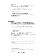
14.2.7
Mirror
Mirror is used to define the instrument type - Moving head or Moving
mirror and the maximum Pan and Tilt angles through which the
instrument can move. These values are required for the 3D tracking
system. Typically a MIRROR line looks like:-
MIRROR 1 170 110
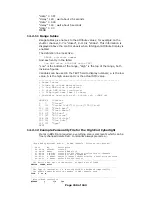
Where:-
MIRROR is the keyword
1 indicates moving mirror a 2 in this field indicates a moving head


