Hercules-EBX CPU User Manual V1.02
Page 42
6.4 Watchdog Timer
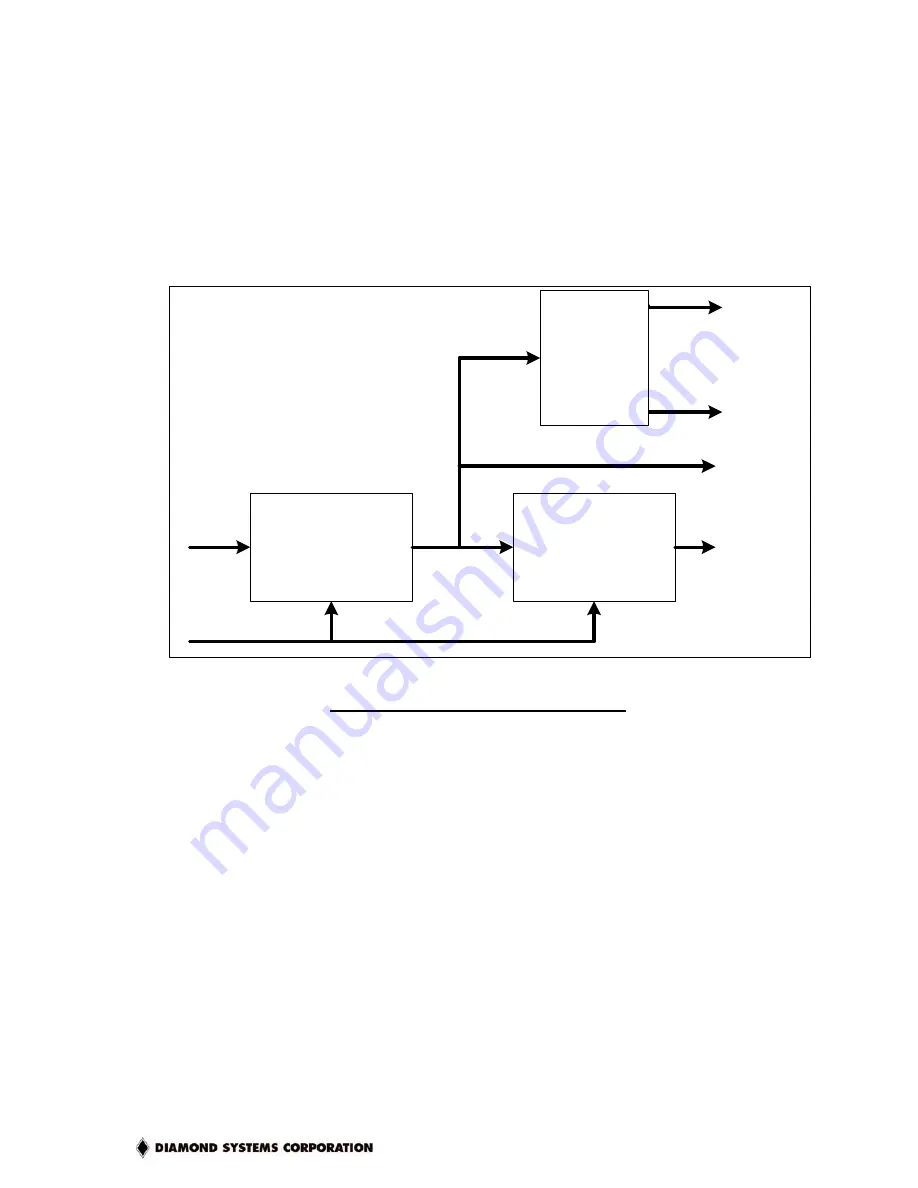
Hercules-EBX contains a watchdog timer circuit consisting of two programmable timers, WD1 and
WD2, cascaded together. The input to the circuit is WDI, and the output is WDO. Both signals
appear on Digital I/O connector J8. WDI may be triggered in hardware or in software. A special
“early” version of WDO may be output on the WDO pin. When this signal is connected to WDI, the
watchdog circuit will be retriggered automatically. A block diagram is provided here:
WDI
10kHz
WD1
16-bit counter
6.5535 sec
max.
WD2
8-bit counter
0.0255 sec
max.
MUX
RESET
WDO
RESET
SMI
Figure 9 : Watchdog Timer Block Diagram
The duration of each timer is user-programmable. When WD1 is triggered, it begins to count
down. When it reaches zero, it triggers WD2, sets WDO high, and may also generate a user-
selectable combination of these events:
♦
System Management interrupt (SMI)
♦
Hardware reset
WD2 then begins to count down. When WD2 counter reaches zero, it will unconditionally cause a
hardware reset. The WD2 timer is provided to give external circuits time to respond to the WDO
event before the hardware reset occurs.
The watchdog timer circuit is programmed via I/O registers located on Page 0: Base +28-31
Detailed programming can be found on page. The Hercules-EBX watchdog timer is supported in
the DSC Universal Driver software version 5.7 and later.


