Hercules-EBX CPU User Manual V1.02
Page 97
See sections on “Counter / Timer Operation” on page 99 and “DIO Handshaking Mode” (below)
for details on these special functions (available only when DIOCTR1 is set to “1”).
13.9.1 DIO HANDSHAKING OPERATION
Normally, the DIO data is transferred through the data registers with each read. If a handshaking
method is desired, two signals are provided to allow this type of transfer:
•
DIOLATCH
o
Input to system (low latches all input data; high passes data through directly)
o
Normally pulled-up (passes all DIO data through without handshaking); affected by
DIO pull-up’s
o
Falling edge generates IRQ when “DINTE” (Base+13, bit 5) is “1”
o
Present on DIO Header J8, pin 39
o
NOTE : Only accessible when “DIOCTR is set to “1”
•
ACK
o
Output from system (driven high when DIOLATCH transitions from high-to-low; ACK
is driven low as soon as latched data is read into the system)
o
Present on DIO Header J8, pin 43
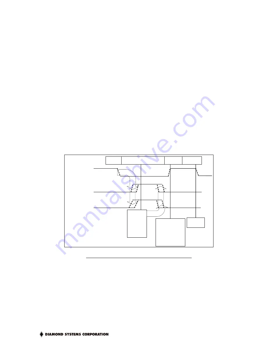
The handshaking sequence would look similar to this over the course of one data transaction:
Causes
DIOLATCH
(IN)
ACK (OUT)
DINT (to
onboard
ADIRQ)
1
0
1
0
IRQ
Software
Responds
to DINT:
Reads
DIO Data
Causes
External
Hardware
Responds to
ACK by sending
new data and
Toggling
DIOLATCH
Cycle
Restarts
DIO Data Valid
(IN - at
connector)
VALID
<Unused>
INVALID
VALID
Figure 10 : DIOLATCH / ACK Handshaking Diagram
13.9.2 DIO PULL-UP/DOWN SETTINGS
All DIO signals have some basic ESD and over/under-voltage protection. In addition, all signals
can be configured with pull-up or pull-down resistors to set a given I/O voltage when no input
signal is provided. This pull-up/pull-down setting should always be made for two reasons:
1. Prevents floating inputs (latch-up from floating input where CMOS I/O pins are involved)
2. Sets a known voltage level for inputs that are not driven


