Chapter 8 Register Structure
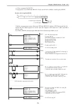
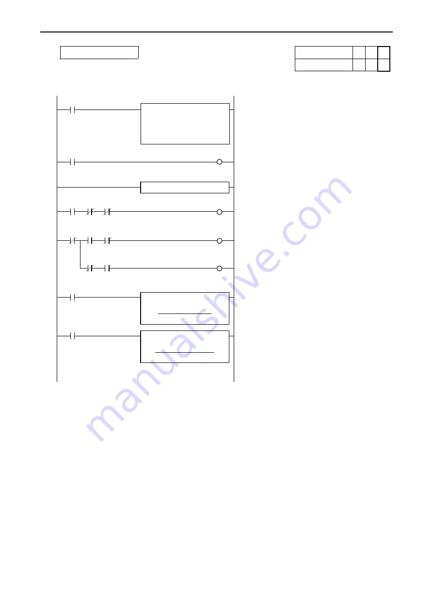
Sample program 9
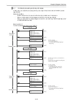
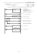
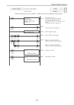
To write to Control Register
Slot No.
0
1
2
(for EHV-CPU)
EH-ETH2
-
-
*
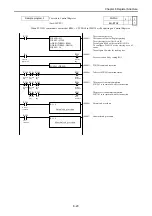
When SCRW command is executed at R200 = 1, WM110 to WM119 will be putting on Control Register.
R1
(00001)
To set s parameter area
The request of Control Register putting
To set the target area (Unit 0, slot2)
To configure WM110 as the starting area of
source
To configure 10 words for sending size
R7E3
(00003)
(00002)
R200
To set execution bit by setting R1=1
SCRW command execution
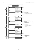
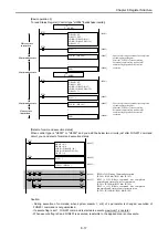
Normal end procedure
Abnormal end procedure
SCRW (WR008, R200)
CR write
Request bit
R200
WR00B = H3
WR00C = H200
DR00D = ADR (WM110)
WR00F = 10
R203
R201
R202
Normal
flag
Execute
flag
Error
flag
Execute
flag
During
execution
R200
R204
R201
R202
Normal
flag
Execute
flag
Error
flag
Normal
condition
R205
R201
R202
Normal
flag
Error
flag
Error
condition
R1 = 0
:
Normal end procedure
:
R204
R1 = 0
:
Abnormal end procedure
:
R205
Normal
condition
Error
condition
(00004)
(00005)
(00006)
(00007)
To detect SCRW command status
The process is normal completion
SCRW is in status of wait for instruction.
The process is abnormal completion
SCRW is in status of wait for instruction.
8-21

