Chapter 9 Maintenance, check, error
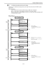
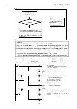
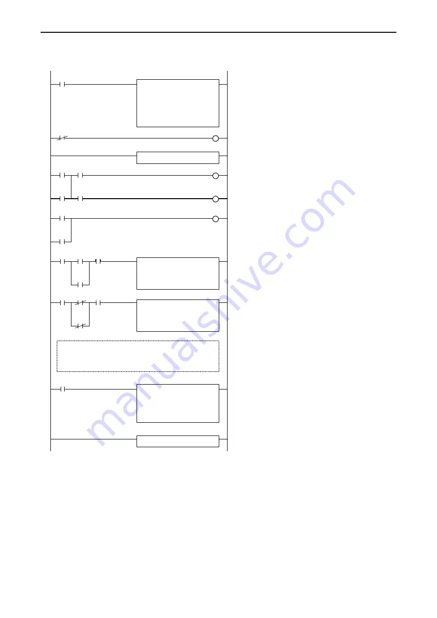
(c-2) By user program (for EHV-CPU)
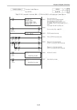
The below user program is the sample which converted (c-1) into for EHV-CPUs.
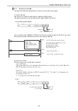
SCRW for reading out SR
SCRW (WM000, R100)
(00003)
(00001)
WM003 = H2
WM004 = H2F
DM005 = ADR (WM10)
WM007 = 1
R100 = 13
(00002)
R100
S
Reading out SR at R100 = 1
R100
Set SCRW(s) parameter area.
Request to SR read
Set EH-ETH2 installation position(unit 0, slot0)
Set head of I/O No. WM10.
Set read size 1 word
Set SR read control bit 1.
R7E3
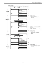
(00004)
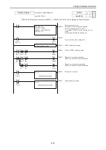
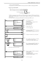
M200
Check the status of ERR and IER LED, if detecting an
open error at connection 1.
If each LED turns on, set the lights out instruction bit.
M110
Set 1 to “request to write to CR bit”, if it passes for
five seconds after detecting an open error.
Validate the lights out demand cancellation circuit
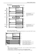
(00006)
R103 = 1
R104 = 0
R1 = 0
R3 = 1
(0000x)
R7E3
WM00B = H3
WM00C = H0
DM00D = ADR (WM20)
WM00F = 10
SCRW (WM008, R103)
(0000y)
Parameter area setting of SCRW(s) for writing CR.
Request to write CR.
Area setting (unit:0, slot:0)
Transmission I/O address is starting from WM20.
Transmission data size is 10 words.
SCRW for writing CR
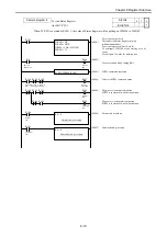
Set 1 to “request to write to CR bit”, if the lights out
instruction bit of ERR or IER LED is cleared.
Validate the lights out demand cancellation circuit
(00007)
M201
M100
M101
TD64 M200
M201
R104 M200
M201
R103 = 1
R104 = 0
R3 = 0
R4 = 1
R3
R3
(00005)
TD64
If the lights out instruction bit is set, start the timer.
M200
M201
1s
5
DIF
ASR connection 1 open request retries circuit
9-5

