FCU 500, FCU 505 · Edition 02.17
2
▼
= To be continued
Protective system controls FCU 500, FCU 505 . . . . . . 1
Contents . . . . . . . . . . . . . . . . . . . . . . . . . . . . . . . . . . . . . . . . . . . . 2
1 Application . . . . . . . . . . . . . . . . . . . . . . . . . . . . . . . . . . . . . . . . 5
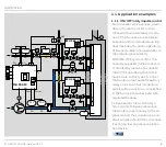
1.1 Application examples . . . . . . . . . . . . . . . . . . . . . . . . . . . . . . 8
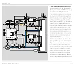
1.1.1 ON/OFF rotary impulse control . . . . . . . . . . . . . . . . . . . . . . .8
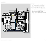
1.1.2 Modulating burner control . . . . . . . . . . . . . . . . . . . . . . . . . . 10
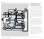
1.1.3 Safety limits (LDS) for modulating burner control . . .11
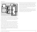
1.1.4 Flame control using the temperature . . . . . . . . . . . . . . . 12
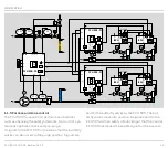
1.1.5 Furnace and zone control . . . . . . . . . . . . . . . . . . . . . . . . . . . 13
2 Certification . . . . . . . . . . . . . . . . . . . . . . . . . . . . . . . . . . . . . .14
3 Function . . . . . . . . . . . . . . . . . . . . . . . . . . . . . . . . . . . . . . . . . .15
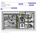
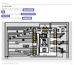
3.1 Connection diagram . . . . . . . . . . . . . . . . . . . . . . . . . . . . . .15
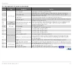
3.1.3 Assignment of connection terminals . . . . . . . . . . . . . . . .17
3.2 Program sequence. . . . . . . . . . . . . . . . . . . . . . . . . . . . . . . .19
3.2.2 FCU 500..F1, FCU 500..F2. . . . . . . . . . . . . . . . . . . . . . . . . . 20
3.2.3 FCU 505..F1, FCU 505..F2 . . . . . . . . . . . . . . . . . . . . . . . . . . .21
3.3 Animation . . . . . . . . . . . . . . . . . . . . . . . . . . . . . . . . . . . . . . . . .22
4 Temperature monitoring . . . . . . . . . . . . . . . . . . . . . . . . . 23
4.1 High temperature operation with safety
temperature monitor function (STM function) . . . . . . .24
4.1.1 With integrated STM . . . . . . . . . . . . . . . . . . . . . . . . . . . . . . . . 24
4.1.2 With external STM. . . . . . . . . . . . . . . . . . . . . . . . . . . . . . . . . . . 25
4.1.3 With integrated and external STM . . . . . . . . . . . . . . . . . . 25
4.2 Maximum temperature monitoring with
(flue gas) safety temperature limiter (STL/FSTL
4.2.1 With integrated STL/FSTL . . . . . . . . . . . . . . . . . . . . . . . . . . 26
4.2.2 With external STL/FSTL . . . . . . . . . . . . . . . . . . . . . . . . . . . . 26
5 Air control . . . . . . . . . . . . . . . . . . . . . . . . . . . . . . . . . . . . . . . .27
5.1 Controlled air flow . . . . . . . . . . . . . . . . . . . . . . . . . . . . . . . .28
5.2 Capacity control . . . . . . . . . . . . . . . . . . . . . . . . . . . . . . . . . .29
6 Furnace zone control . . . . . . . . . . . . . . . . . . . . . . . . . . . . .31
7 Valve proving system . . . . . . . . . . . . . . . . . . . . . . . . . . . . 33
7.1 Tightness control. . . . . . . . . . . . . . . . . . . . . . . . . . . . . . . . . .34
7.1.2 One test volume between 2 gas solenoid valves . . . . 36
7.1.3 One test volume for system tightness . . . . . . . . . . . . . . . 39
7.1.4 Two test volumes for system tightness . . . . . . . . . . . . . . 42
7.1.5 Large test volumes with reduced testing time . . . . . . 46
. . . . . . . . . . . . . . . . . . . . . . . . . . . . . . . . . . . . . 48
for system tightness . . . . . . . 48
7.2.3 For two test volumes for system tightness (V
7.2.4 Extended valve opening time 1 t
. . . . . . . . . . . . . . . . . . 50
. . . . . . . . . . . . . . . . . . . . . . . . . . . . . . . 53
7.3 Proof of closure function . . . . . . . . . . . . . . . . . . . . . . . . . . 57
8 BCSoft . . . . . . . . . . . . . . . . . . . . . . . . . . . . . . . . . . . . . . . . . . . 58
9 Fieldbus communication via Ethernet . . . . . . . . . . . 59
9.1 FCU and bus module BCM . . . . . . . . . . . . . . . . . . . . . . 60
9.2 Configuration, planning . . . . . . . . . . . . . . . . . . . . . . . . . . 61
9.2.1 Profinet/Device master data file (GSD) . . . . . . . . . . . . . .61
9.2.3 Modules/Registers for process data. . . . . . . . . . . . . . . . 62
9.2.4 Device parameters and statistics . . . . . . . . . . . . . . . . . . . 68
10 Program step/status . . . . . . . . . . . . . . . . . . . . . . . . . . . 69
11 Fault signalling . . . . . . . . . . . . . . . . . . . . . . . . . . . . . . . . . 70
12 Parameters . . . . . . . . . . . . . . . . . . . . . . . . . . . . . . . . . . . . . .74
12.2.1 Emergency stop. . . . . . . . . . . . . . . . . . . . . . . . . . . . . . . . . . . . 79
12.2.2 High gas pressure protection . . . . . . . . . . . . . . . . . . . . . . 80
12.2.3 Low gas pressure protection. . . . . . . . . . . . . . . . . . . . . . . 80
12.2.4 Low air pressure protection . . . . . . . . . . . . . . . . . . . . . . . . .81
Contents


