α
2 Simple Application Controllers
Function Blocks 6
6 - 18
6.9
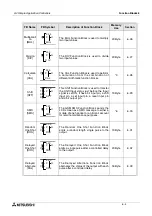
Flicker Block
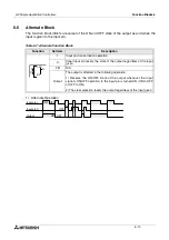
The function block provides a method to give a patterned ON/OFF Output signal. The user can
set independent ON and OFF times for the Output. The output pattern can be dependent on an
input signal, or can be performed for a preset cycle time or number of repetitions.
Table 6.10: Flicker Function Block
Note: The set time cannot be less than one scan time for the controller; otherwise, the
Flicker Function Block will not perform its assigned task for the time specified. Users
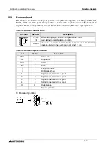
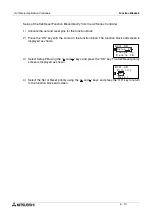
can monitor the scan time from the
α
2
Series Controller. Scan time is dependent on
the user-program; therefore, caution is needed as and when time units are selected.
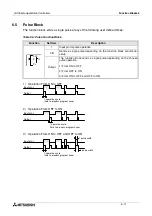
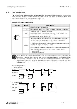
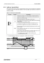
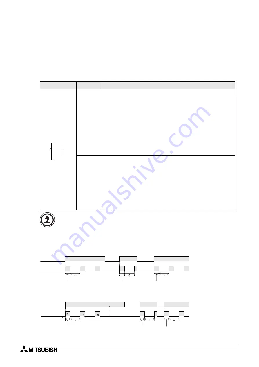
Flicker Operation
1 ) Continuous control action
2 ) Frequency control action
Function
Set Item
Description
I
Input pin for flicker operation
FB
The following three set items exist:
1) The applicable range for the turning the output ON is 0s to 32767s
Time intervals are 10ms, 100ms or 1s (*Note)
2) The applicable range for the turning the output OFF is 0s to 32767s
Time intervals are 10ms, 100ms or 1s (*Note)
3) Blinking operation
a) Cycles count (frequency assigned operation) maximum
number of cycles to be set is 32767
b) Time count maximum 32767
c) Continuous control
Output
The control operations provides an ON/OFF state for the output.
1) The output state directly reflects the ON and OFF condition of the
input signal at the input pin.
2) The following items are available for other function blocks:
a) On Flicker
b) Current On Flicker
c) Off Flicker
d) Current Off Flicker
e) Cycle or Time
f) Current Cycle or Time
0
0
0
L
F
O
I
P
Input pin I
Output
ON OFF
ON
OFF
On time
Off time
On time
Off time
On time
Off time
Input pin I
Output
ON OFF
ON
OFF
On time
Off time
On time
Off time
On time
Off time
registered number of times
once
twice
three
times
once
once
twice

