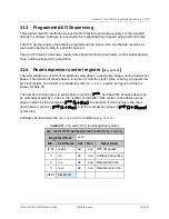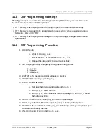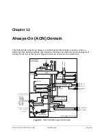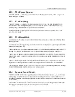
PMU registers may be read without setting
pmukey
.
14.4
PMU Program
The PMU is implemented as a programmable sequencer to support customization and tuning of
the wakeup and sleep sequences. A wakeup or sleep program comprises eight instructions. An
instruction consists of a delay, encoded as a binary order of magnitude, and a new value for all
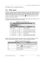
of the PMU output signals to assume after that delay. The PMU instruction format is shown in
Table 35. For example, the instruction
0x108
delays for
clock cycles, then raises
hfclkrst
and lowers all other output signals.
The PMU output signals are registered and only toggle on PMU instruction boundaries. The out-
put registers are all asynchronously set to 1 by
aonrst
.
PMU Instruction Format (
pmu(sleep/wakeup)iX
)
Register Offset
0x100
Bits
Field Name
Attr.
Rst.
Description
[3:0]
delay
RW
X
delay multiplier
4
pmu_out_0_en
RW
X
Drive PMU Output En 0 High
5
pmu_out_1_en
RW
X
Drive PMU Output En 1 High
7
corerst
RW
X
Core Reset
8
hfclkrst
RW
X
High-Frequency Clock Reset
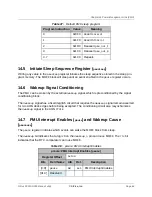
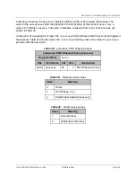
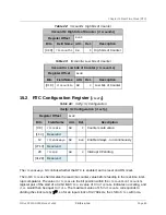
At power-on reset, the PMU program memories are reset to conservative defaults. Table 36
shows the default wakeup program, and Table 37 shows the default sleep program.
Program Instruction
Value
Meaning
0
0x1F0
Assert all resets and enable all power supplies
1
0x1F8
Idle
cycles, then deassert
hfclkrst
2
0x030
Deassert
corerst
and
padrst
3-7
0x030
Repeats
Table 35:
PMU Instruction Format
Table 36:
Default PMU wakeup program
Chapter 14 Power-Management Unit (PMU)
SiFive FE310-G000 Manual: v3p2
© SiFive, Inc.
Page 65

