Page | 34
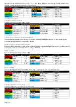
Option
Description
Labels
Custom
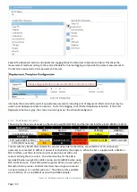
Universal Inputs.
Provides a set of 4 terminals that may be rewired internally to
suit customer specific applications, such as providing access to additional analog
inputs, terminals in parallel to an already available terminal (such as additional
SW12V, G or C1 connections), or for use with a customer supplied component. Two
terminals U1 and U2 are provided, with 2 additional power terminals
SW12V
G
U2
U1
Com Port Interfaces
RS485
Converts normal RS232 port into a RS485 serial port for use with 2-wire half duplex
instruments.
SW12V
G
RS485_B
RS485_A
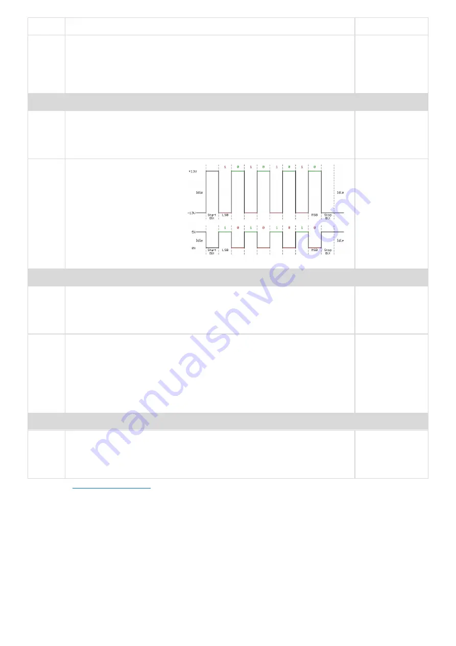
UART
Converts normal RS232 port into
a UART serial port for use with
instruments that require UART
voltage levels. RS232 voltages
are normally ±13V, while UART
voltages are normally 0-5V and
inverted. The four-terminal
provided are Tx, Rx, SW12V and
G.
SW12V
G
Tx
Rx
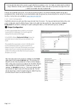
Power Output Peripherals
Power
Switch
The power switch provides 3 high current outputs from the normally low power
outputs A3, A4 and PSW. Inside the electronics housing are 3 x 5V regulators with
an output current up to 800mA. 4 terminals are provided, one each for the boosted
A3, A4 and PSW outputs and an additional Ground (G)
A3
A4
PSW
G
Relay
Output
The relay output peripheral provides two independently controlled dry contact
switch outputs from the A3 and A4 outputs. Each relay output is a separate pair of
Common (C) and Normally Open outputs. For example, a relay connected to A3
input has the common terminal wired to A3+ and the normally open terminal wired
to A3-. Similarly, the relay connected to A4 has its own common terminal wired to
A4+ and the normally open terminal to A4+. While the relay is rated to 8A, the
contacts should only be used for up to 2A due to the wire sizes used internally.
A3+
A3-
A4+
A4-
Miscellaneous
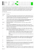
EXO SOA The electronics housing may include an EXO Signal Output Adapter (SOA) to convert
the proprietary EXO signal to an SDI12 output. This port connects to the same
labelled ports on the SOA. Refer to the EXO SOA documentation for further details.
RED
BLACK
YELLOW
WHITE
Refer to the
for more detailed specifications on the I/O and program functionality.
4.1.5
Internal Status Sensors
The Ai1 provides extensive internal status monitoring to help diagnose operational problems remotely. All status
sensors are read periodically (SLOW_MEASUREMENT_INTERVAL) or can be manually triggered by setting
ReadStatusSensors to True.
Humidity
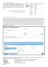
The humidity sensor indicates if the internal desiccant is still effective or needs replacement. The humidity reading is
viewed from the
InternalHumidity
public variable or the logged data. The internal humidity measurement is
indicative (±8%) and anything over 80% is likely to have internal condensation. It is critical that internal humidity be
monitored and alarmed as internal condensation can cause significant
damage that is not covered by warranty. Internal humidity is managed
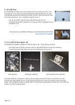
Figure 14 - Orange (dry), Green (moist)


