Page | 50
contact sales for advice)
14
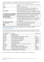
. To set up a DCS, the following settings are recommended. Items highlighted bold are
required for the DCS to communicate with the Ai1 and for the Ai1 to decode results correctly.
STOP
If the sensor is currently running measurements. This may need to be
repeated
GET ALL
Show all the available settings
HELP
Show all the available commands. To see all modes with an
enumerated parameter, view the options under “Argument List for
enumerated properties” at the end of the help message
SET PASSKEY(1)
Passkey level 1 gives permission to write most parameters, although
some may require Passkey level 1000. If a set command results in the
message “ERROR PROTECTED PROPERTY”, a higher passkey is required.
SET MODE(SMART SENSOR TERMINAL)
Changes between modes such as AiCaP and the serial terminal mode.
SET ENABLE DECIMALFORMAT(YES)
Display values in decimal format, i.e. 0.000 instead of 0.000E+00
SET ENABLE TEXT(NO)
Set data reports to be numbers only, no text headers
SET PING NUMBER(50)
The number of pings for a reading, options 50, 60, 75, 100,
…, 600
SET POLLED PINGRATE(10.0)
The number of pings per second, options 0.1, 0.5, 1.0, 2.0, 5.0, 10.0,
15.0, 20.0, 25.0. Note it must include the decimal. The result of Ping
Number/Ping Rate should be less than 10 so that one reading is
returned each 10s
SET ENABLE POLL MODE(NO)
Does not require polling, transmits based on an interval
SET INTERVAL(10)
The number of seconds between data output reports
SAVE
Save the settings to non-volatile memory
RESET
Run the sensor with the new settings
The DCS does not have a function to reset to factory defaults so it is best to check each configuration parameter
listed above for correct values. For a listing of all factory defaults, a file is available for download:
www.measci.com/dcs_default.txt
The Ai1 controls power to the sensor so that it is only turned on when required, and off in-between readings. The
readings returned by the DCS which may be displayed in Hydrosphere, Eagle.io or other platforms list in Table 9.
Table 9 - DCS Parameter Names
Parameter Name
Description
Default Units
DCS_Model
DCS Model, i.e., 4830
DCS_SN
DCS Serial Number
Abs_Speed
Average Absolute Current Speed (vector averaged)
cm/s
Direction
Current Direction of Abs_Speed vector
Degrees (°)
Nth_Vector
North component of current direction
Degrees (°)
Eth_Vector
East component of current direction
Degrees (°)
Heading
Last measured compass heading
Degrees (°)
Tilt_X
Tilt in X direction of DCS
Degrees (°)
Tilt_Y
Tilt in Y direction of DCS
Degrees (°)
SP_Std
Single Ping standard deviation of all pings in measurement
cm/s
Sig_Strength
Signal Strength
dB
Ping_Count
Number of pings used in measurement
pings
Abs_Tilt
Absolute tilt (relative to horizontal plane) of DCS
Degrees (°)
Max_Tilt
Maximum tilt (relative to horizontal plane) of DCS
Degrees (°)
Std_Tilt
Standard deviation of tilt measurements
Degrees (°)
DCS_Temp_ZPulseOnly Temperature (only fitted on Z pulse models)
°C
#Do I have decimal mode on or not? It displays zero as 0.000. I think I should have it on.
14
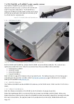
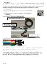
To set up for communication with a PC, connect Green to DB9 pin 2, White to DB9 pin 3 and Black to Ai1 GND. DCS remains powered by Ai1. The terminal must be set up with CR+LF line feeds.

