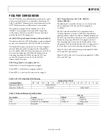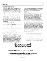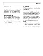
ADV7181B
Rev. B | Page 67 of 100
I
2
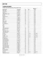
C REGISTER MAP DETAILS
The following registers are located in Register Access Page 2.
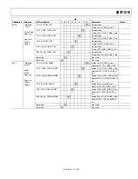
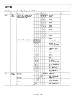
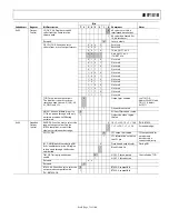
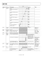
Table 83. Interrupt Register Map Bit Names
Subaddress
Register
Name
Reset
Value
rw
Dec Hex Bit 7
Bit 6
Bit 5
Bit 4
Bit 3
Bit 2
Bit 1
Bit 0
Interrupt
Config 0
0001 x000
rw
64
0x40
INTRQ_
DUR_SEL.1
INTRQ_
DUR_SEL.0
MV_INTRQ
_SEL.1
MV_INTRQ
_SEL.0
MPU_
STIM_INTRQ
INTRQ_
OP_SEL.1
INTRQ_
OP_SEL.0
Reserved
65
0x41
Interrupt
Status 1
r
66
0x42
MV_PS_
CS_Q
SD_FR_
CHNG_Q
SD_
UNLOCK_Q
SD_LOCK_
Q
Interrupt
Clear 1
x000 0000
w
67
0x43
MV_PS_
CS_CLR
SD_FR_
CHNG_CLR
SD_UNLO
CK_CLR
SD_LOCK
_CLR
Interrupt
Maskb 1
x000 0000
rw
68
0x44
MV_PS_
CS_MSKB
SD_FR_
CHNG_
MSKB
SD_
UNLOCK_
MSKB
SD_LOCK
_MSKB
Reserved
69
0x45
Interrupt
Status 2
r
70
0x46
MPU_
STIM_
INTRQ_Q
WSS_
CHNGD_Q
CGMS_
CHNGD_Q
GEMD_Q CCAPD_Q
Interrupt
Clear 2
0xxx 0000
w
71
0x47
MPU_
STIM_INT
RQ_CLR
WSS_
CHNGD_
CLR
CGMS_
CHNGD_
CLR
GEMD_
CLR
CCAPD_
CLR
Interrupt
Maskb 2
0xxx 0000
rw
72
0x48
MPU_
STIM_INT
RQ_MSKB
WSS_CHN
GD_MSKB
CGMS_
CHNGD_
MSKB
GEMD_
MSKB
CCAPD_
MSKB
Raw Status 3
r
73
0x49
SCM_
LOCK
SD_H_
LOCK
SD_V_
LOCK
SD_OP_
50HZ
Interrupt
Status 3
r
74
0x4A
PAL_SW_
LK_
CHNG_Q
SCM_
LOCK_
CHNG_Q
SD_AD_
CHNG_Q
SD_H_
LOCK_
CHNG_Q
SD_V_
LOCK_
CHNG_Q
SD_OP_
CHNG_Q
Interrupt
Clear 3
xx00 0000
w
75
0x4B
PAL_SW_
LK_CHNG
_CLR
SCM_
LOCK_
CHNG_CLR
SD_AD_
CHNG_
CLR
SD_H_
LOCK_
CHNG_CLR
SD_V_LO
CK_CHNG
_CLR
SD_OP_
CHNG_CLR
Interrupt
Maskb 3
xx00 0000
rw
76
0x4C
PAL_SW_
LK_CHNG
_MSKB
SCM_
LOCK_CH
NG_MSKB
SD_AD_
CHNG_
MSKB
SD_H_
LOCK_CH
NG_MSKB
SD_V_
LOCK_CH
NG_MSKB
SD_OP_
CHNG_
MSKB
1
To access the Interrupt Register map, the bits of the register access page[1:0] in Register Address 0x0E must be programmed to 01b.


