31
Byte 1
Byte 2
Byte 3
Byte 4
Byte 5
Byte 6
Byte 7
Byte 8
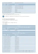
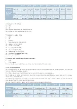
Frame 1
Basis-ID+0
Standard:
700h
Contents
Status
Physical inputs
Status soft inputs
Unit
-
-
Conversion
Bit flags
(1)
Bit flags
(1)
Data type
Unsigned
Unsigned
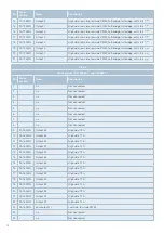
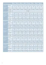
Frame 2
Basis-ID+1
Standard:
701h
Contents
opState01 opState02 opState03 opState04 opState05 opState06 opState07 opState08
Unit
-
-
-
-
-
-
-
-
Conversion
Coding output state
(2)
Data type
Unsigned
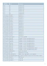
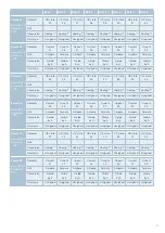
Frame 3
Basis-ID+2
Standard:
702h
Contents
opState09 opState10 opState11 opState12 opState13 opState14 opState15 opState16
Unit
-
-
-
-
-
-
-
-
Conversion
Coding output state
(2)
Data type
Unsigned
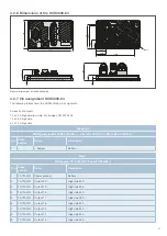
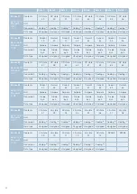
Frame 4
Basis-ID+3
Standard:
703h
Contents
opState17 opState18 opState19 opState20 opState21 opState22 opState23 opState24
Unit
-
-
-
-
-
-
-
-
Conversion
Coding output state
(2)
Data type
Unsigned
7.2 Integral electronic load protection, troubleshooting
The intelligent SCS1000 and SCS3000 power distribution systems have an integral electronic load protection.
In addition to disconnecting the individual load outputs in the event of an overcurrent or short circuit on the individual channel, this
also includes the possibility of defining warning thresholds and implementing separate tripping characteristics for inrush currents.
If outputs are defined as a team, an overload on one channel will cause all channels of the team to trip.
The trip current and the trip time of the load protection can be set for each channel via PDUsetup. This also applies to the trip
behaviour in the event of an inrush and the configuration of the warning thresholds.
A tripping in case of too low current, undervoltage or too high board temperature is also configurable.
By means of a CAN message, the SCS1000 and SCS3000 signal the respective error condition, as well as the affected load output
(see also datastream in chapter 7.3.1 to 7.3.3).
After the error has been eliminated, the channels can be switched on again remotely. This is done on the software side by sending
a corresponding CAN message (see chapter 7.6), or via the physical reset input pin.
7.3 PDU datastream
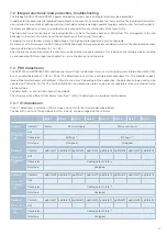
The SCS1000 and SCS3000 PDUs continuously transmit input and output states, as well as load current information via the CAN
bus at an adjustable rate of 1 HZ to 100 Hz. The datastream is sent from a software-definable »base ID«. The modules support
three different datastreams with different CAN data structures. Depending on the application, the datastream to be used can be
selected via PDUsetup. For the V2 and V3 datastream, the transmission rate can also be set separately for each individual frame
via the software.
The datastream is sent via CAN channel 1 by default.
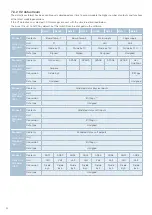
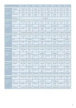
The structure of the different CAN frames from the V1 to the V3 datastream is described in detail below.
7.3.1 V1 datastream
If the V1 datastream is selected, CAN messages are sent with the structure described below.
The base ID is set to 0x700 by default, but this initial ID can be changed via the software.

