52
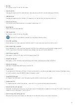
Name
Symbol
Description
Menu options
(Right click on symbol)
Event In
For activating special PDU features and
behaviours, such as resetting the module
via hardware pin, sending serial number
and SW version via CAN, keeping module
active/awake, etc.
Setting the event (reset, lamp, Power_
Hold, CAN_ver_Tx)
Out state
For further processing of PDU-internal
states and events, such as module tem-
perature, voltage supply, potential of the
wake pin, tripping of a channel, etc.
Setting the event (Fault, Wake, Re-
set_SW, Tot_Current, Power_V, Logic_V,
Board_Temp)
Value
A defined analogue value
None
Comparitor
Compares two values and sets output
high or low depending on the defined
comparison
Selection of the comparison function
(greater than, less than, equal, unequal)
and setting of a hysteresis
Maths operation
Performs the selected mathematical
operation with the applied values A and B
and makes the analogue value available
at the output.
Selection of the mathematical operation
(add, subtract, multiply, divide, min, max).
A soft input refers to an input received via CAN. A soft output refers to an output value sent via CAN.
Examples of how the individual symbols and components can be used can be found in the example configuration provided during
software installation (see also 8.3.4).
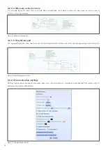
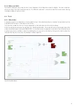
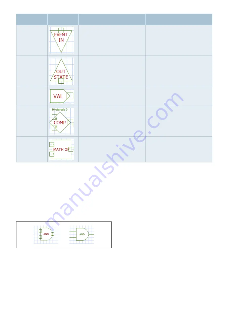
The text of a component appears green when it is fully defined and red as soon as not all values and properties are set (figure 18).
A component is defined when all its input and output nodes are used and the properties are set correctly.
It is mandatory that all input pins are used before simulation or programming. Output pins can be left free to allow testing of sub-
systems and partial logic, but remain highlighted in red.
Figure 18: Symbol definition

