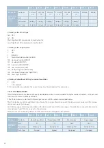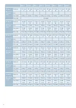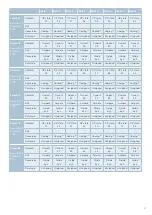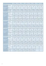
50
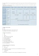
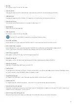
Name
Symbol
Description
Menu options
(Right click on symbol)
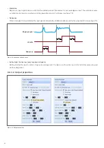
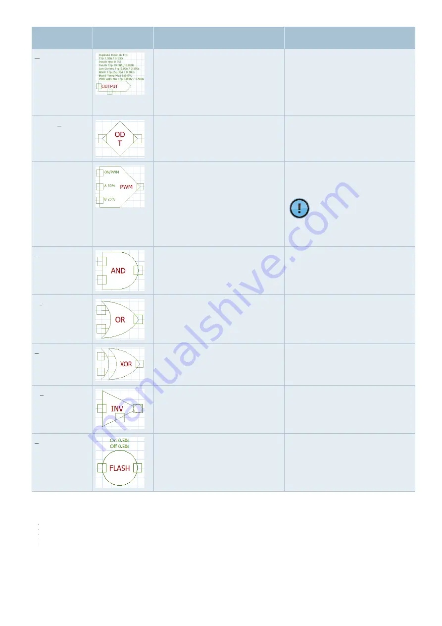
Output
Physical output or soft output
Physical outputs have a »status output«
that acts as a bypass when the output
trips.
- Fix output. If the output is fixed, all
connected components are also locked
and displayed in yellow. These
components cannot be edited or moved
until the output is unlocked again.
- Add or remove the status output.
- Other features (see 8.3.3.2)
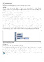
Output distributor
Output distributor for multiple outputs.
Merged outputs (team) trip simultane-
ously.
Switch between individual or team
distribution.
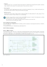
PWM
Control of the PWM duty cycles of a
PWM-capable output. Priority of the input
pins from top to bottom. Multiple PWM
components can be linked together, to
get more duty cycle options. If a soft
input controls the PWM symbol, the duty
cycle can be flexibly set via the value of
the soft input (-1 ... -100 corresponds to
the duty cycle in percent).
Setting duty cycle A and
duty cycle B
The duty cycle of a PWM output
can also be set directly via
analogue values at the output.
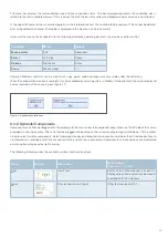
And
Logical AND switches when all inputs are
high.
Adding or removing additional input pins
Or
Logical OR switches when one more
inputs are high.
Adding or removing additional input pins
Xor
Logical exclusive OR switches when only
one input is high.
Adding or removing additional input pins
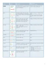
Invert
Logical negation. Invert the input.
Adding or removing the input control pin.
Causes the inverter to operate only when
the input is active.
Flash
Switching between high and low at set
intervals
Setting the On/Off switching time.


