44
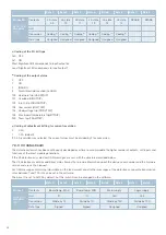
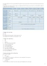
Bits 2 - 4: Datastream version
0
V2 datastream
1
V3 datastream
Bits 5 - 7 not in use
(4)
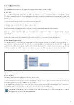
Coding of modular version
0x10 SCS3000-34
0x11 SCS3000-48
0x12 SCS3000-64
0x13 SCS3000-16
7.4 Soft I/Os
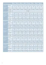
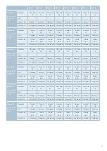
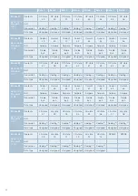
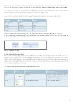
Soft inputs and soft outputs communicate via 8 bit elements. Each CAN frame has 8 inputs or 8 outputs with adjustable addresses.
The preset default IDs for the different datastreams are structured as follows:
V1 datastream:
64 soft inputs from 710 ... 717h in numerical order
64 soft outputs from 718 ... 71Fh in numerical order
V2 datastream:
64 soft inputs from 730 ... 737h in numerical order
64 soft outputs from 738 ... 73Fh in numerical order
V3 datastream:
128 soft inputs from 740 ... 74Fh in numerical order
64 soft outputs from 750 ... 757h in numerical order
These addresses and the transmission rate of the soft outputs can be changed under »Cal«, »Communication« in the PDUsetup
software. The integration and activation of CAN keypads reduces the number of available inputs and outputs, as some of them
are reserved for the keypad control.
The soft input byte is considered as »signed«. Zero means that the soft input is switched off, a positive value means that the soft
input is switched on or the respective analogue value is evaluated. A negative value means no change.
Analogue values received via soft inputs can be further processed within the software and used for calculations. If a soft input is
directly connected to a PWM-capable module output in the programme, the positive value of the soft input byte defines the PWM
duty cycle in percent.
However, soft inputs can also be used in combination with the PWM symbol to control the duty cycle in PWM applications. In this
case, the negative value of the soft input byte defines the duty cycle in percent (-1 ... -100 corresponds to 1 % ... 100 %).
Analogue values present at the module inputs or values calculated in the programme can be sent via the CAN bus within soft outputs.
7.5 Keypad connection
By activating the »Switch Panel« checkboxes in the »Cal«, »Communication« dialogue box, the integration of keypads can be
activated. CAN-capable keypads from the manufacturers Grayhill and Blink are supported.
Some soft I/Os are reserved for the connection of the keypads, thus enabling the assignment of inputs and outputs to the inputs
of the keypads and for LED feedback.
7.6 Error reset
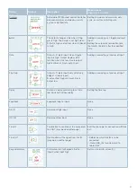
There are two ways to reset an error. To reset on the hardware side, the corresponding reset pin must be briefly pulled to ground.
On the software side, every valid CAN frame with the »Fault Reset« identifier configured via PDUsetup is accepted as a reset
command by the module.

