51
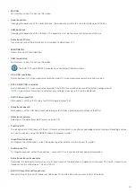
Name
Symbol
Description
Menu options
(Right click on symbol)
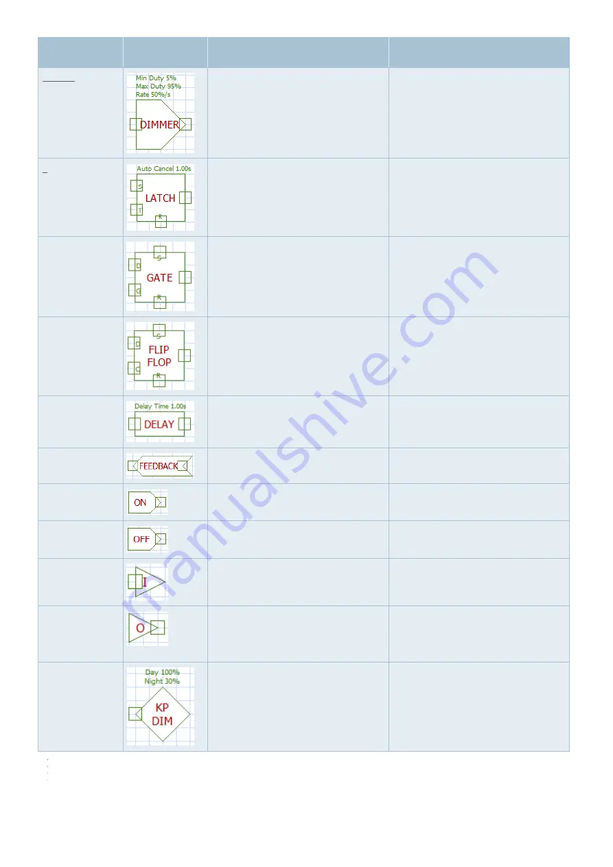
Dimmer
Adjustable PWM output control. Switches
between minimum and maximum duty
cycle at a defined rate
Setting minimum and maximum duty
cycle, as well as switching rate
Latch
The output changes state when T (Tog-
gle) is high. The output is set high when
S (Set) is high and set low when R (Reset)
is high.
Adding or removing set, toggle and reset
input.
Setting the automatic termination time
that resets the latch after the specified
time.
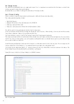
Gate
Output = D (data input) when G (gate
input) is high. Output displays latch
function when G is low. S sets output
high until reset, R sets output low.
Adding or removing set and reset input
Flip Flop
Output = D (data input) only with rising
edge at C (clock input).
S sets output high until reset, R sets
output low.
Adding or removing set and reset input
Delay
Switch-on delay according to set time
lag. Switch off without delay.
Setting the time lag
Feedback
Feedback loop to inputs
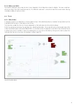
None
ON (1)
Permanent high input
None
OFF (0)
Permanent low input
None
Link IN
Termination to continue at the associated
link OUT (may be on another page)
Edit the link name for connection with link
out.
Link OUT
Continuation of the signal from link IN
(may be on another page)
- Determine which link IN is to be
connected
- »Goto LINK_IN« for quick jump to
related link
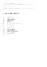
Keypad dimmer
Dimmer control for keypads. Set to
'Night' when input high
Set max. and min. values (%)


