Parker Hannifin S.p.A S.B.C. Division
SLVDN User’s Manual
Page 171 of 181
13.1.11.2.
Use of controlword and statusword
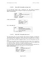
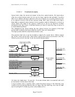
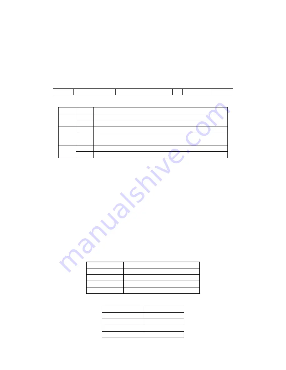
The cyclic synchronous position mode uses no mode specific bits of the controlword and
three bits of the statusword for mode-specific purposes. Figure 64 shows the structure of the
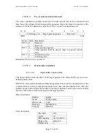
statusword. Table 236 defines the values for bit 10, 12, and 13 of the statusword.
15 14
13
12
11
10
9
0
Following error
Target position ignored
Reserverd
MSB
LSB
Name Value Description
0 Reserved
Bit 10
1 Reserved
0
Target position ignored
Bit 11
1
Target position shall be used as input to position control
loop
0
No following error
Bit 12
1 Following
error
Definition of bit 10, bit 12, and bit 13
13.1.11.3.
Detailed object definitions
13.1.11.3.1.
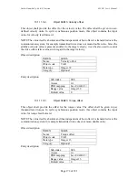
Object 60B0
h
: Position offset
This object shall provide the offset of the target position. The offset shall be given in user-
defined position units.
NOTE The value itself is absolute and thus independent of how often it is transmitted over the
communication system, for example, transmitted twice does not mean double value. Since the
additive position value represents an offset to the target position it can be also used to control
the drive with relative values with regard to the target position.
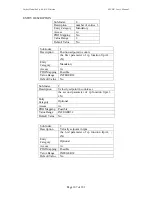
Object description
INDEX
60B0h
Name
Position offset
Object code
VAR
Data type
INTEGER 32
Category
Optional
Entry description
Sub-index 00h
Access
rw
PDO mapping
See /CiA402-3/
Range value
Integer 32
Default value
0


