7-26
Inputs, Outputs, Timers, and Other Control Logic
Date Code 20011205
SEL-311B Instruction Manual
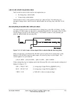
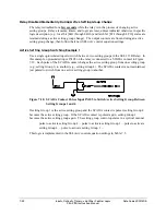
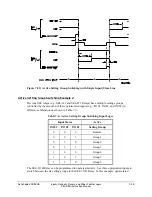
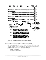
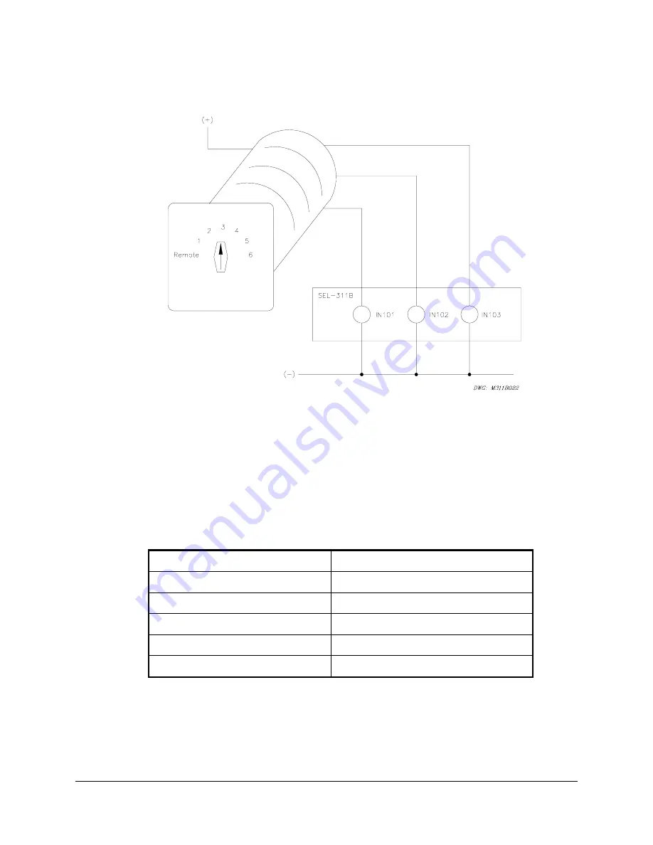
inputs IN101, IN102, and IN103 on the relay are connected to a rotating selector switch in Figure
Figure
7.21: Rotating Selector Switch Connected to Inputs IN101, IN102, and IN103 for
Active Setting Group Switching
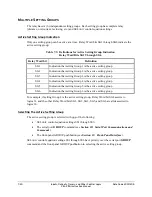
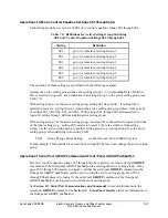
The selector switch has multiple internal contacts arranged to assert inputs IN101, IN102, and
IN103, dependent on the switch position. As shown in Table
7.7, when the selector switch is
moved from one position to another, a different setting group is activated. The logic in Table
is implemented in the SEL
OGIC
control equation settings in Table
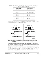
Table
7.7: SEL
OGIC
Control Equation Settings for Rotating Selector Switch
Active Setting Group Switching
SS1 = !IN103 * !IN102 * IN101
= NOT(IN103) * NOT(IN102) * IN101
SS2 = !IN103 * IN102 * !IN101
= NOT(IN103) * IN102 * NOT(IN101)
SS3 = !IN103 * IN102 * IN101
= NOT(IN103) * IN102 * IN101
SS4 = IN103 * !IN102 * !IN101
= IN103 * NOT(IN102) * NOT(IN101)
SS5 = IN103 * !IN102 * IN101
= IN103 * NOT(IN102) * IN101
SS6 = IN103 * IN102 * !IN101
= IN103 * IN102 * NOT(IN101)
The settings in Table
7.7 are made in each setting Group 1 through 6.
Summary of Contents for SEL-311B
Page 6: ......
Page 8: ......
Page 10: ......
Page 24: ......
Page 26: ......
Page 122: ......
Page 124: ......
Page 138: ......
Page 168: ......
Page 172: ......
Page 254: ......
Page 282: ......
Page 306: ......
Page 348: ......
Page 364: ......
Page 366: ......
Page 448: ......
Page 460: ......
Page 466: ......
Page 476: ......
Page 482: ......
Page 494: ......
Page 500: ......
Page 522: ......
Page 526: ......
Page 528: ......
Page 534: ......
Page 536: ......
Page 550: ......
Page 570: ......
Page 586: ......
Page 600: ......


