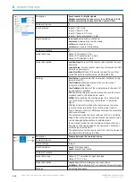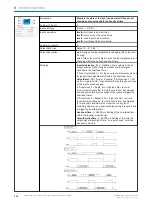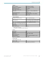
NOR
Table 33: Thruth table
Input
A
Input
B
Out‐
put
1
1
0
1
0
0
0
1
0
0
0
1
Description
Combine the input signals with a logical NOR.
Number of inputs
4
Input data type
1-bit (future extension: or n-bit)
Input description
levelA:
first input
levelB:
second input
levelC:
third input
levelD:
fourth input
Maximum 4 inputs can be linked together. If you want to link
more signals, you can work with several NOR blocks.
Number of outputs
1
Output data type
Identical to input data type
Output description
level:
the output depends on the various inputs. For more
information see truth table
Settings
No settings available
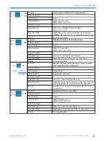
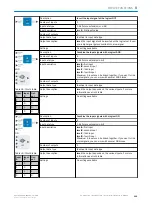
XNOR
Table 34: Thruth table
Input
A
Input
B
Out‐
put
1
1
1
1
0
0
0
1
0
0
0
1
Description
Combine the input signals with a logical XNOR.
Number of inputs
2
Input data type
1-bit (future extension: or n-bit)
Input description
levelA:
first input
levelB:
second input
levelC:
third input
levelD:
fourth input
Maximum 4 inputs can be linked together. If you want to link
more signals, you can work with several XNOR blocks.
Number of outputs
1
Output data type
Identical to input data type
Output description
level:
the output depends on the various inputs. For more
information see truth table
Settings
No settings available
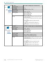
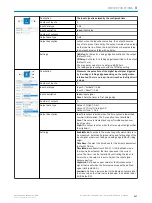
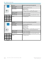
NOTE
Please be aware that the Integer values have a value range from 0....65.535. There is no overflow or underflow
indication.
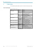
NOTE
The logic editor does only support integers (e. g. 2) and no decimal numbers (e. g. 2,345). In case, the calculated
result would be a decimal number, the logic editor will round up or down.
DEVICE FUNCTIONS
8
8017853.1D0S/2021-11-04 | SICK
O P E R A T I N G I N S T R U C T I O N | Sensor Integration Gateway - SIG200
121
Subject to change without notice

