4–3
T-372
4.2 Controller Software
The controller software is a custom designed program that is subdivided into configuration software and opera
-
tional software. The controller software performs the following functions:
• Control supply or return air temperature to required limits, provide modulated refrigeration operation, econo
-
mized operation, unloaded operation, electric heat control, and defrost. Defrost is performed to clear buildup
of frost and ice to ensure proper air flow across the evaporator coil.
• Provide default independent readouts of setpoint and supply or return air temperatures.
• Provide ability to read and (if applicable) modify the configuration software variables, operating software
function codes and alarm code indications.
• Provide a pre-trip step-by-step checkout of refrigeration unit performance including: proper component oper
-
ation, electronic and refrigeration control operation, heater operation, probe calibration, pressure limiting and
current limiting settings.
• Provide battery-powered ability to access or change selected codes and setpoint without AC power con
-
nected. This is only if the carrier-provided rechargeable battery option is installed.
4.2.1
Configuration Software (CnF Variables)
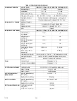
Configuration software is a variable listing of the components available for use by the operational software. This
software is factory installed in accordance with the equipment fitted and options listed on the original purchase
order. Changes to the configuration software are required only when a new controller has been installed or a phys
-
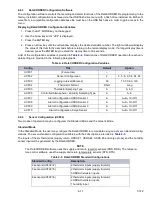
ical change has been made to the unit such as the addition or removal of an option. A configuration variable list is
provided in
. Change to the factory-installed configuration software can be achieved via the controller
micro USB port.
4.2.2
Operational Software (Cd Function Codes)
Operational software is the actual operation programming of the controller which activates or deactivates compo
-
nents in accordance with current unit operating conditions and selected modes of operation. The programming is
divided into function codes. Some of the codes are read only, while the remaining codes may be user configured.
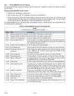
The value of the user configurable codes can be assigned in accordance with user desired mode of operation. A
list of the function codes is provided in
4.2.2.a Accessing Function Codes on the Display
1. Press the CODE SELECT key on the keypad.
2. Press an Arrow key until the left window displays the desired function code.
3. The right window will display the selected function code value for five seconds before returning to normal
display mode.
4. If additional time is required, press the ENTER key to extend the display time to 30 seconds.
4.3 Modes of Operation
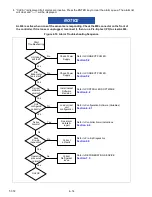
General operation sequences for cooling, heating and defrost are provided in the following sub-sections. Sche
-
matic representation of controller operation is provided in
,
Operational software responds to various inputs. These inputs come from the temperature sensors and pressure
transducers, the temperature setpoint, the settings of the configuration variables and the function code assignments.
The action taken by the operational software changes as the input values change. Overall interaction of the inputs is
described as a “mode” of operation. The modes of operation include perishable (chill) mode and frozen mode. Descrip
-
tions of the controller interaction and modes of operation are provided in the following sub-sections.
4.3.1
Start Up - Compressor Phase Sequence
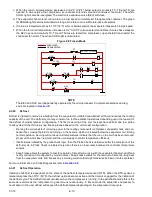
At start up, the controller logic checks for proper phase sequencing and compressor rotation. If incorrect sequenc
-
ing is causing the compressor and three-phase evaporator fan motors to rotate in the wrong direction, the controller
will energize or de-energize relay TCP as required. Relay TCP will switch its contacts, energizing or de-energizing
relays PA and PB. Relay PA is wired to energize the circuits on L1, L2 and L3. Relay PB is wired to energize the cir
-
cuits on L3, L2, and L1, thus providing reverse rotation.

