Appendix 2. Flag List
APP2 - 7
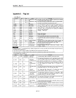
7) Communications Flag
- GLOFA Mnet / Fnet / Cnet Flag List
(1) Communication Module Information Flag List
•
n is the number of slot where a communications module is loaded. ( n = 0 to 7)
Keyword
Type
Applicable
Net
Name
Description
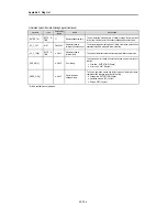
_CnVERNO
UINT
Mnet/Fnet/Cnet
Communications module
version No.
•
Communications module O/S version No.
_CnSTNOH
_CnSTNOL
UINT
UDINT
Mnet/Fnet/Cnet
Communications module station
No.
•
Indicates the number which is set on communications module station switch.
Mnet : MAC station No. marked on the front of communication module.
Fnet : Station switch No. marked on the front of communications module.
Cnet : Station No. set by the frame editor
_CnSTNOH : Station No. set on the side of RS-232C
_CnSTNOL : Station No. set on the side of RS-422
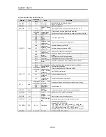
_CnTXECNT
UINT
Mnet/Fnet/Cnet
Communications frame sending
error
•
Increments by one whenever sending error of communications frame occurs.
•
Connection condition of network is evaluated by this value.
•
In Cnet, this value is the sum of errors occurred during receiving through RS-
232 and RS-422.
_CnRXECNT
UINT
Mnet/Fnet/Cnet
Communications frame
receiving error
•
Increments by one whenever communications service fails.
•
Connection condition of network is evaluated by this value. Overall network
communications quantity and program stability are also evaluated by this
value.
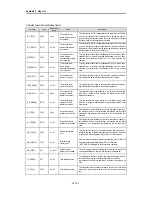
_CnSVCFCNT
UINT
Mnet/Fnet/Cnet
Communications service
processing error
•
Indicates the maximum time that is spent until every station connected to
network has the token at least one time and sends a sending frame.
_CnSCANAV
UINT
Mnet/Fnet/Cnet
Maximum communications scan
time (unit : 1 ms)
•
Indicates the average time that is spent until every station connected to
network has the token at least one time and sends a sending frame.
_CnSCANMN
UINT
Mnet/Fnet/Cnet
Average communications scan
time (unit : 1 ms)
•
Indicates the minimum time that is spent until every station connected to
network has the token at least one time and sends a sending frame.
_CnLINF
_CnLNKMOD
_CnINRING
_CnIFERR
_CnSVBSY
_CnCRDER
UINT
BIT 15
BIT 14
BIT 13
BIT 12
BIT 11
Mnet/Fnet/Cnet
Minimum communications scan
time (unit : 1 ms)
Operation mode (RUN=1,
TEST=0)
In-ring (IN_RING = 1)
Interface error (error = 1)
Insufficient common RAM
(Insufficient = 1)
Communications module
system error (error = 1)
•
Indicates operation state of communications module with a word.
•
Indicates that operation mode of co mmunications module is in the normal
operation mode or test mode.
•
Indicates that the communications module can communicates(IN_RING = 1)
with other station or not.
•
Indicates that interface with communications modules has been stopped.
•
Indicates that service cannot be offered due to insufficient common RAM.
•
Indicates communications module hardware defect or system O/S error.
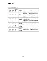
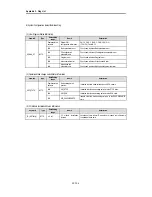
_NETn_LIV[k]
( k = 0 to 63,
k:Station No. )
BIT
ARRAY
Fnet
Stations connected to the
network (1=connected,
0=disconnected)
•
Indicates whether k remote station or local PLC is connected to the network
or not. The state value is written to each bit. These values shows present
state of the network. (Write is disabled)
_NETn_RST[k]
( k = 0 to 63,
k:Station No. )
BIT
ARRAY
Fnet
Re-connection of a station
(1=re -connected, 0=no changed
condition)
•
Indicates re -connected stations, which had been disconnected before, on a
bitmap. Because this value has been replaced with ‘1’ when re -connected,
the user program has to clear this value with ‘0’ so that next re -connection
can be detected. (Write is enabled)
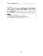
_NETn_232[k]
( k = 0 to 63,
k:Station No. )
BIT
ARRAY
Cnet
The indication that the user
defined frame has been
received. Indicated at each
setting No. (Received = 1).
•
When a receiving frame is received through RS-232C while the part of RS-
232C in Cnet is operating in the user-defined mode, the bit corresponding to
setting No. is turned ON. If RCV_MSG F/B has read that, that bit will be
cleared with 0.
_NETn_4 22[k]
( k = 0 to 63,
k:Station No. )
BIT
ARRAY
Cnet
The indication that the user
defined frame has been
received. Indicated at each
setting No. (Received = 1).
•
When a receiving frame is received through RS-422 while the part of RS-
232C in Cnet is operating in the user-defined mode, the bit corresponding to
setting No. is turned ON. If RCV_MSG F/B has read that, that bit will be
cleared with 0.

