


4.2 Using the Sequence Function
59
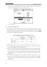
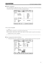
the end of the step is suspended, and the execution transitions to the step of the next number
when Resume instruction is detected.
--------
Notes
----------------------------------------------------------------------------------------------------------------
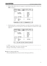
When [Step Term] is set to [Hold], the execution enters into hold state before jump. Jumps
when Resume instruction is detected.
When [Step Term] is set to [Hold], after the jumps repeated for the specified Jump count,
the execution transitions to the step of the next number when Resume instruction is
detected in hold state.
While in the hold state due to the step termination in a step where step termination phase
is enabled, the execution transitions to Jump-to step or the step of next number when
Resume instruction is detected, after the hold state is kept until Stop Phase.
---------------------------------------------------------------------------------------------------------------------------------
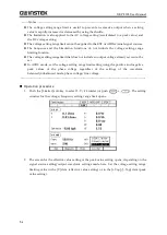
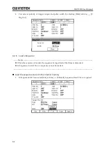
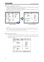
Step sync code output (Code)
State output to CONTROL I/O connector. Code to output while the execution of the step,
which is specified by 2-bit H/L.
Start Phase (StartPhs)
Determines the phase of AC waveform of L1 phase when the step starts.
--------
Notes
----------------------------------------------------------------------------------------------------------------
Step Start Phase setting can be disabled. In that case, the phase when the phase starts
becomes the phase when the previous step ended.
In DC mode, the step Start Phase cannot be set.
---------------------------------------------------------------------------------------------------------------------------------
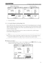
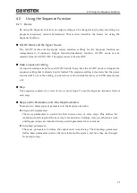
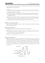
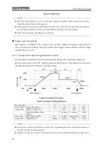
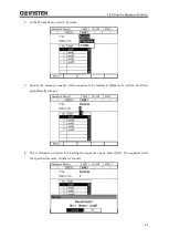
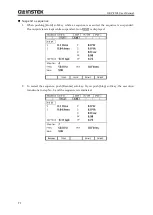
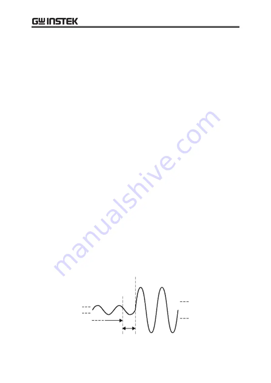
Stop Phase (Stop Phs)
Determine the phase of AC waveform when the step ends. When the stop phase setting is active,
the execution waits for the Step Time that was set pass, and keeps the output setting until it
reaches the Stop Phase that was set, and then transitions to the next step. As the result, the
actual step time is longer by one cycle at a maximum than the set Step Time. Figure 4-3 shows
an example where both the Stop Phase of the previous step and the Start Phase of the next step
are set to 0°.
Next step
Previous step
Step Time finished
Waiting for stop phase
Summary of Contents for GKP-2302
Page 15: ...1 1 OUTLINE 1 1 Overview 2 1 2 Features 2...
Page 28: ...GKP 2302 User Manual 14 Nothing is connected to the output terminal...
Page 60: ......
Page 186: ......
Page 187: ...173 5 DESCRIPTION OF SCREEN AND MENU 5 1 Screen Configuration 174 5 2 Menu Composition 177...
Page 195: ...181 6 REMOTE CONTROL 6 1 Communication Interface 182 6 2 Remote Local State Switching 188...
Page 216: ......
Page 222: ......


