70
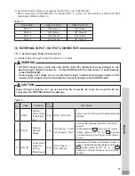
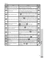
Pin
No.
Code
Function
Input /
Output
Description
4
RESET
Error
Release
Input
' ON (Closed) '
→
' OFF (Open) '
Error Code can be released and the system
restarted by toggling this signal OFF and
ON. Error will not be released until cause of
the error has been removed.
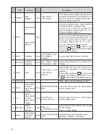
5
SEL
1
Motor Select
1
Input
―
Use when selecting motor, after connecting
CONTROLLER to the SELECTOR.
4
motors can be selected by SEL
0
and
SEL
1
combination. Refer to P
69
"
15
-
2
–
2
(
7
) Motor Selection Table.
4
.")
Speed Point
Select
1
When only using CONTROLLER, Speed Point
Signal can be selected. Speed Point (U
1
- U
4
)
can be selected by SEL
0
and SEL
1
signal
combination. Refer to P
68
"
15
-
2
-
2
(
5
)
③
Set by the Speed Point Signal " section.
Need to set parameter
. (Refer to P
90
"
18
-
4
⑤
Selection of External Speed
Control Mode " section.)
6
RUN
Rotating
Output
' OFF (Open) ' : Stop
' ON (Closed) ' :
Rotating
Output shows that the motor is rotating.
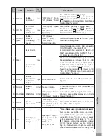
7
DIR_OUT
Rotating
Direction
Output
' OFF (Open) ' : FWD.
' ON (Closed) ' : REV.
Output shows the direction of the Motor is
rotating.
8
ERR
Error
Output
' OFF (Open) ' : Error
' ON (Closed) ' :
Normal
Output shows that error has occurred. Error
code will be displayed on Digital Speed
Indicator
⑪
.
When setting parameter
, Error Output
Mode can be changed. (Refer to P
88
"
18
-
4
①
Setting of Error Output Mode " section.)
9
Not used
―
―
―
*Note : Never use pin labeled not used.
10
GND
Internal GND
for Motor
Speed Control
Voltage
Output
Internal CONTROLLER
GND
This GND will be used for " Motor Speed
Control Voltage (VR) ".
11
Vcc
Internal
Power Source
for Motor
Speed Control
Voltage
Output
Internal Power
Source : DC+
10
V
Internal Power Source for " Motor Speed
Control Voltage (VR) ".
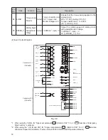
12
MOTOR_I
Motor
Current
Monitor
Output
2
Amp / V,
0
V
≦
MOTOR_I
≦
10
V
Output Motor Current Monitor with Analog
Monitor Voltage.
2
Amp /
1
V. Max.
20
Amp.
13
GND
Internal GND
for Analog
Monitor
Output
Internal CONTROLLER
GND
This GND will be used for analog monitor
(MOTOR_I, SPEED_V, and LOAD).


