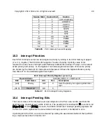
Individual interrupts are enabled by setting the appropriate bit in the
mie
register. The
mie
regis-
ter is described in Table 20.
Machine Interrupt Enable Register
CSR
mie
Bits
Field Name
Attr.
Description
[2:0]
Reserved
WPRI
3
MSIE
RW
Machine Software Interrupt Enable
[6:4]
Reserved
WPRI
7
MTIE
RW
Machine Timer Interrupt Enable
[10:8]
Reserved
WPRI
11
MEIE
RW
Machine External Interrupt Enable
[31:12]
Reserved
WPRI
Table 20:
mie
Register
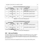
The machine interrupt pending (
mip
) register indicates which interrupts are currently pending.
The
mip
register is described in Table 21.
Machine Interrupt Pending Register
CSR
mip
Bits
Field Name
Attr.
Description
[2:0]
Reserved
WIRI
3
MSIP
RO
Machine Software Interrupt Pending
[6:4]
Reserved
WIRI
7
MTIP
RO
Machine Timer Interrupt Pending
[10:8]
Reserved
WIRI
11
MEIP
RO
Machine External Interrupt Pending
[31:12]
Reserved
WIRI
Table 21:
mip
Register
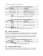
When a trap is taken in machine mode,
mcause
is written with a code indicating the event that
caused the trap. When the event that caused the trap is an interrupt, the most-significant bit of
mcause
is set to 1, and the least-significant bits indicate the interrupt number, using the same
encoding as the bit positions in
mip
. For example, a Machine Timer Interrupt causes
mcause
to
be set to
0x8000_0007
.
mcause
is also used to indicate the cause of synchronous exceptions, in
which case the most-significant bit of
mcause
is set to 0.
See Table 22 for more details about the
mcause
register. Refer to Table 23 for a list of synchro-
nous exception codes.
Copyright © 2019, SiFive Inc. All rights reserved.
39
Summary of Contents for FE310-G002
Page 1: ...SiFive FE310 G002 Manual v19p05 SiFive Inc ...
Page 11: ...Figure 1 FE310 G002 top level block diagram Copyright 2019 SiFive Inc All rights reserved 9 ...
Page 15: ...Chapter 2 List of Abbreviations and Terms 13 ...
Page 23: ...Chapter 4 Memory Map The memory map of the FE310 G002 is shown in Table 4 21 ...

