The
pwmsticky
bit disallows the
pwmcmp
ip
registers from clearing if they are already set and
is used to ensure interrupts are seen from the
pwmcmp
ip
bits.
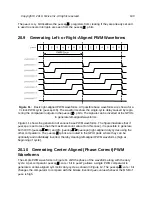
Generating Left- or Right-Aligned PWM Waveforms
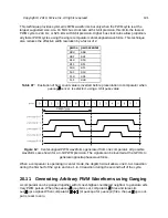
Figure 11:
Basic right-aligned PWM waveforms. All possible base waveforms are shown for a
7-clock PWM cycle (
pwmcmp0
=6). The waveforms show the single-cycle delay caused by regis-
tering the comparator outputs in the
pwmcmp
ip
bits. The signals can be inverted at the GPIOs
to generate left-aligned waveforms.
Figure 11 shows the generation of various base PWM waveforms. The figure illustrates that if
pwmcmp0
is set to less than the maximum count value (6 in this case), it is possible to generate
both 100% (
pwmcmp
0) and 0% (
pwmcmp
pwmcmp0
) right-aligned duty cycles using the
other comparators. The
pwmcmp
ip
bits are routed to the GPIO pads, where they can be
optionally and individually inverted, thereby creating left-aligned PWM waveforms (high at
beginning of cycle).
Generating Center-Aligned (Phase-Correct) PWM
The simple PWM waveforms in Figure 11 shift the phase of the waveform along with the duty
cycle. A per-comparator
pwmcmp
center
bit in
pwmcfg
allows a single PWM comparator to
generate a center-aligned symmetric duty-cycle as shown in Figure 12. The
pwmcmp
center
bit
changes the comparator to compare with the bitwise inverted
pwms
value whenever the MSB of
pwms
is high.
Copyright © 2019, SiFive Inc. All rights reserved.
100
Summary of Contents for FE310-G002
Page 1: ...SiFive FE310 G002 Manual v19p05 SiFive Inc ...
Page 11: ...Figure 1 FE310 G002 top level block diagram Copyright 2019 SiFive Inc All rights reserved 9 ...
Page 15: ...Chapter 2 List of Abbreviations and Terms 13 ...
Page 23: ...Chapter 4 Memory Map The memory map of the FE310 G002 is shown in Table 4 21 ...


