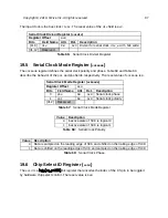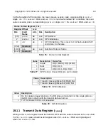
Chip Select ID Register (
csid
)
Register Offset
0x10
Bits
Field Name
Attr.
Rst.
Description
[31:0]
csid
RW
0x0
Chip select ID.
bits wide.
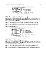
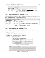
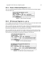
Chip Select Default Register (
The
csdef
register is a
cs_width
-bit register that specifies the inactive state (polarity) of the CS
pins. The reset value is high for all implemented CS pins.
Chip Select Default Register (
csdef
)
Register Offset
0x14
Bits
Field
Name
Attr.
Rst.
Description
[31:0]
csdef
RW
0x1
Chip select default value.
cs_width
bits wide, reset to
all-1s.
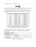
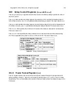
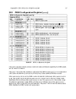
The
csmode
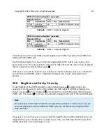
register defines the hardware chip select behavior as described in Table 72. The
reset value is
0x0
(AUTO). In HOLD mode, the CS pin is deasserted only when one of the fol-
lowing conditions occur:
• A different value is written to
csmode
or
csid
.
• A write to
csdef
changes the state of the selected pin.
• Direct-mapped flash mode is enabled.
Chip Select Mode Register (
csmode
)
Register Offset
0x18
Bits
Field Name
Attr.
Rst.
Description
[1:0]
mode
RW
0x0
Chip select mode
[31:2]
Reserved
Value
Name
Description
0
AUTO
Assert/deassert CS at the beginning/end of each frame
2
HOLD
Keep CS continuously asserted after the initial frame
3
OFF
Disable hardware control of the CS pin
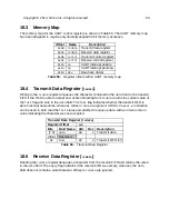
Table 70:
Chip Select ID Register
Table 71:
Chip Select Default Register
Table 72:
Chip Select Mode Register
Table 73:
Chip Select Modes
Copyright © 2019, SiFive Inc. All rights reserved.
88
Summary of Contents for FE310-G002
Page 1: ...SiFive FE310 G002 Manual v19p05 SiFive Inc ...
Page 11: ...Figure 1 FE310 G002 top level block diagram Copyright 2019 SiFive Inc All rights reserved 9 ...
Page 15: ...Chapter 2 List of Abbreviations and Terms 13 ...
Page 23: ...Chapter 4 Memory Map The memory map of the FE310 G002 is shown in Table 4 21 ...


