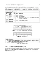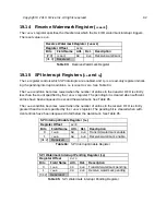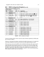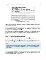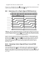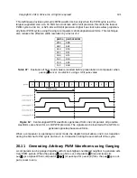
This chapter describes the operation of the Pulse-Width Modulation peripheral (PWM).
Figure 10 shows an overview of the PWM peripheral. The default configuration described here
has four independent PWM comparators (
pwmcmp0
–
pwmcmp3
), but each PWM Peripheral is
parameterized by the number of comparators it has (
ncmp
). The PWM block can generate multi-
ple types of waveforms on output pins (
pwm
gpio
) and can also be used to generate several
forms of internal timer interrupt. The comparator results are captured in the
pwmcmp
ip
flops
and then fed to the PLIC as potential interrupt sources. The
pwmcmp
ip
outputs are further
processed by an output ganging stage before being fed to the GPIOs.
PWM instances can support comparator precisions (
cmpwidth
) up to 16 bits, with the example
described here having the full 16 bits. To support clock scaling, the
pwmcount
register is 15 bits
wider than the comparator precision
cmpwidth
.
94
Summary of Contents for FE310-G002
Page 1: ...SiFive FE310 G002 Manual v19p05 SiFive Inc ...
Page 11: ...Figure 1 FE310 G002 top level block diagram Copyright 2019 SiFive Inc All rights reserved 9 ...
Page 15: ...Chapter 2 List of Abbreviations and Terms 13 ...
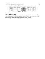
Page 23: ...Chapter 4 Memory Map The memory map of the FE310 G002 is shown in Table 4 21 ...

